Adafruit QT Py + XIAO Expansion board
2022.03.18
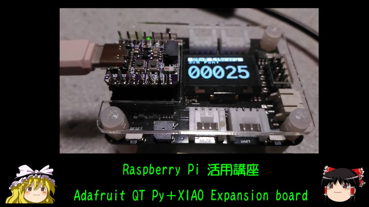
YouTube でも紹介しています。画像をクリックすると再生できます。
Adafruit QT Py シリーズの利便性を、Seeeduino XIAO Expansion boardを使うことで向上させます。
■Adafruit QT Py ESP32-S2 WiFi Dev Board with STEMMA QT
 QT Py ESP32 -S2にはシングルコアの240MHzチップが搭載されているため、デュアルコアのESP32ほど高速ではありませんが、
4MBのフラッシュと2MBのPSRAMを実装しているため、データ解析などに必要なメモリー空間を確保することができます。
QT Py ESP32 -S2にはシングルコアの240MHzチップが搭載されているため、デュアルコアのESP32ほど高速ではありませんが、
4MBのフラッシュと2MBのPSRAMを実装しているため、データ解析などに必要なメモリー空間を確保することができます。
 Adafruit QT Py ESP32-S2
■開発環境
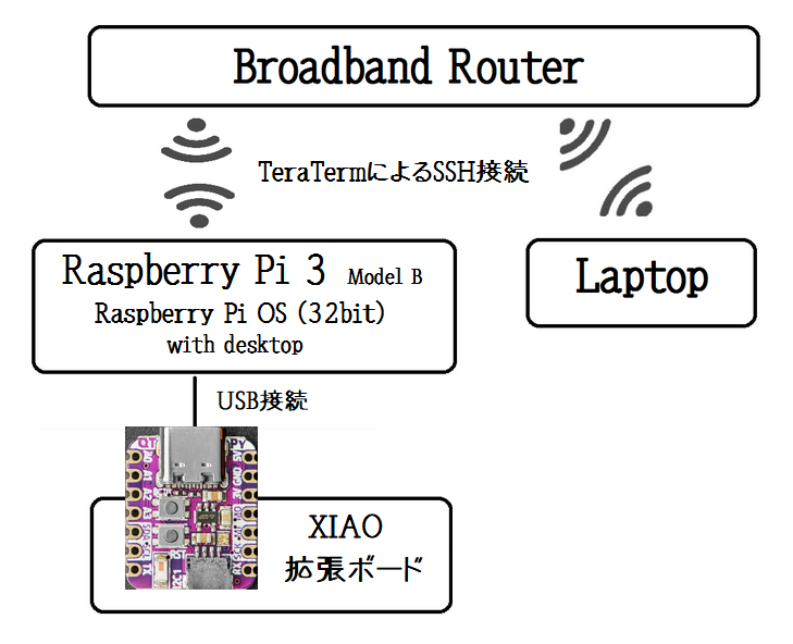
ノートパソコンから、TeraTermによりラズベリーパイにSSH接続して操作します。
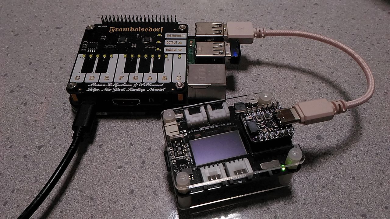
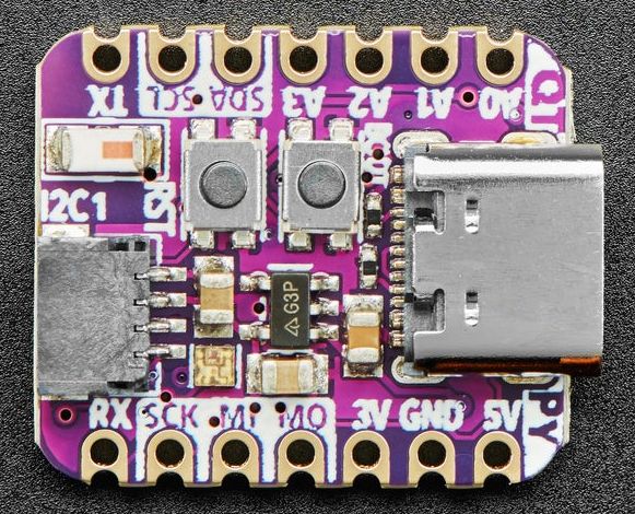
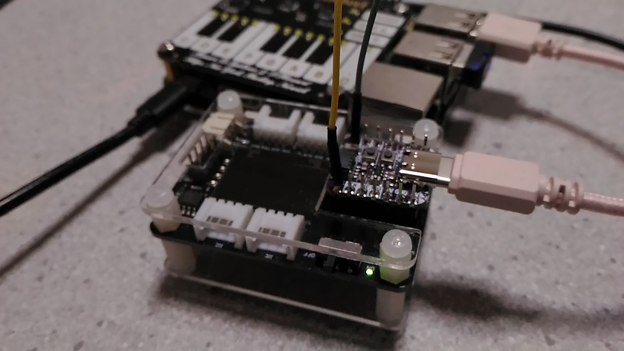
QT Py に両端ロングピンヘッダーをハンダ付けして、Seeeduino XIAO拡張ボードに取り付けています。
ラズベリーパイのOSは、Raspbian GNU/Linux 10 (buster) です。
■Seeeduino XIAO Expansion board
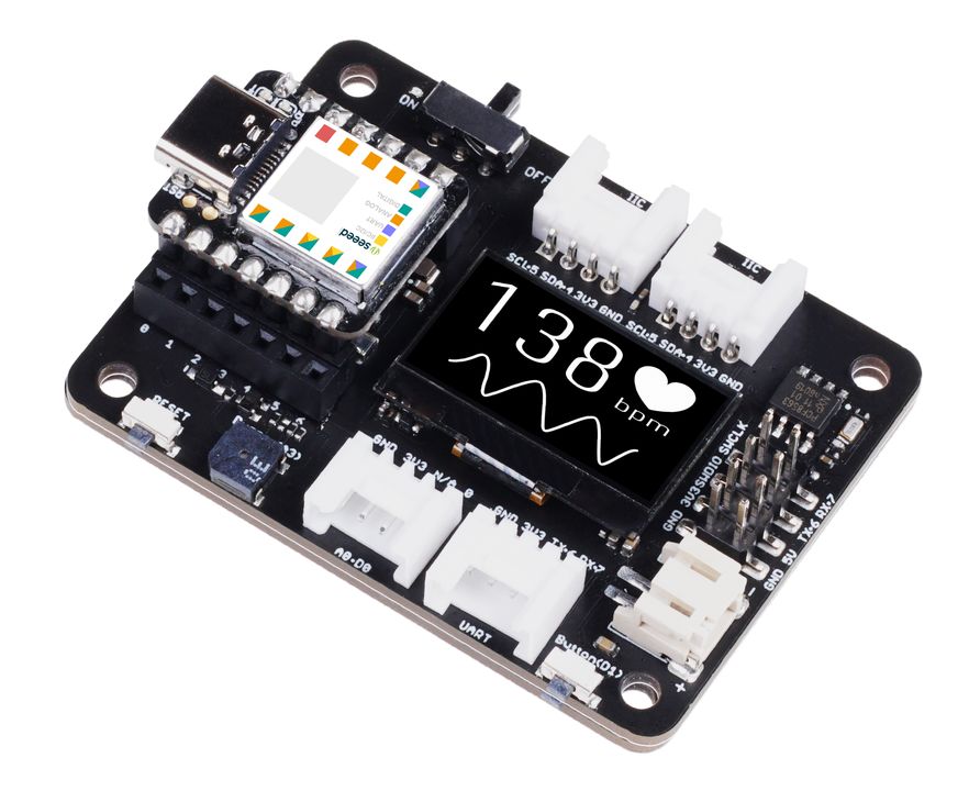
Ref.Seeeduino XIAO Expansion board
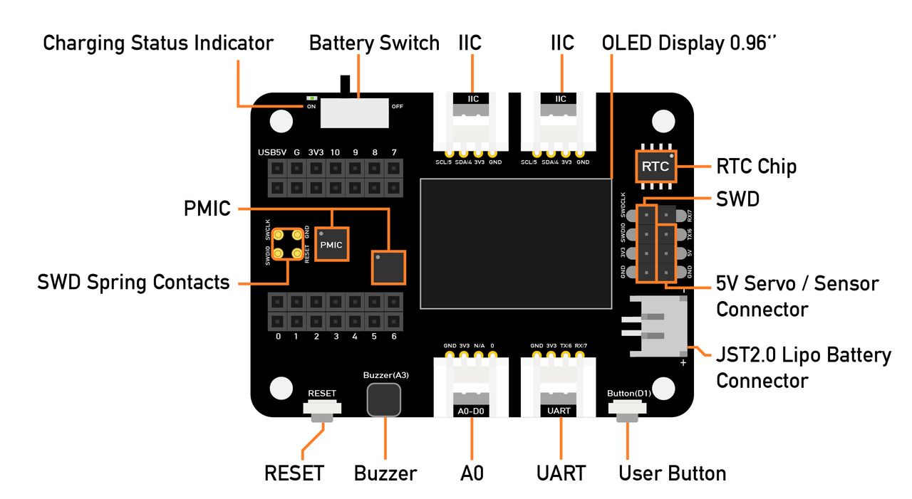
【Specification】
| Operating voltage | 5V / 3.7V Lithium Battery |
| Charging current | 460mA (Max) |
| RTC timer precision | PCF8563T/5 ± 1.5S/DAY(25°C) |
| RTC battery | CR1220 |
| Display | 0.96" OLED display (128x64) |
| Expandable memory | MicroSD card |
| Grove Interface | Grove IIC*2, Grove UART*1, A0/D0 Grove*1 |
| Other External Equipment | Passive buzzer, user button, 5V servo connector |
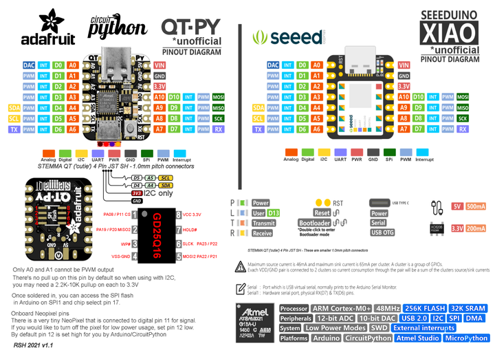
■Adafruit QT PY / Seeeduino XIAO Pinout Cheat Sheet
Adafruit QT PyとSeeeduino XIAOは、ピン配列と形状に互換性があります。
ピン番号は異なりますが、ピン名称を使用すれば、ソースコードを共有できます。
Ref,https://runawaybrainz.blogspot.com/2021/02/adafruit-qt-py-seeeduino-xiao-pinout.html
ビルドには、PlatformIOを使用しています。
Arduino開発環境構築 PlatformIO
■FLASH/PSRAM確認
QT Pyに実装されているPSRAMを確認するプログラムを作ってみます。
プロジェクトを作成します。
$ mkdir ~/QTPyESP32S2
$ cd ~/QTPyESP32S2
$ pio init -b adafruit_qtpy_esp32s2
プログラムを作成します。
$ vi src/checkPSRAM.ino
#include <Wire.h>
#include <SPI.h>
#include <SoftwareSerial.h>
SoftwareSerial mySerial(16, 5); // RX, TX

void setup() {
	mySerial.begin(115200);
	mySerial.printf("Internal Total heap %d, internal Free Heap %d\n", ESP.getHeapSize(), ESP.getFreeHeap());
	mySerial.printf("SPIRam Total heap %d, SPIRam Free Heap %d\n", ESP.getPsramSize(), ESP.getFreePsram());
	mySerial.printf("Flash Size %d, Flash Speed %d\n", ESP.getFlashChipSize(), ESP.getFlashChipSpeed());
	mySerial.printf("ChipRevision %d, Cpu Freq %d, SDK Version %s\n", ESP.getChipRevision(), ESP.getCpuFreqMHz(), ESP.getSdkVersion());
	mySerial.println("");

	int alloc_size = 2000000;
	uint8_t *p = (uint8_t*)malloc(alloc_size);
	if (p == NULL) {
		mySerial.println("Memory Allocate Failed");
	}

	int i = 0;
	while ( i < alloc_size ) {
		p[i] = (char)i;           //値を書き込む
		if ( p[i] != (char)i ) {  //値が合っているかチェック
			mySerial.printf("write error at %d\n", i);
			i--;
			break;
		}
		i++;
	}
	mySerial.printf("%d bytes check Ok\n", i);
	free(p);
}

void loop() {
}
SoftwareSerialライブラリを追加します。
$ pio lib install 168
プログラムの書込みは、QT Py ESP32S2をRaspberry Pi にUSB接続後に、[BOOT]を押しながら[RESET]をクリックして、デバイスをダウンロードモードにします。
$ pio device list
/dev/ttyACM0
------------
Hardware ID: USB VID:PID=303A:0002 SER=0 LOCATION=1-1.4:1.0
Description: ESP32-S2

/dev/ttyAMA0
------------
Hardware ID: 3f201000.serial
Description: ttyAMA0
$ pio run -t upload -e adafruit_qtpy_esp32s2
ERROR: ESP32-S2FH32 chip was placed into download mode using GPIO0.
esptool.py can not exit the download mode over USB. To run the app, reset the chip manually.
To suppress this error, set --after option to 'no_reset'.
*** [upload] Error 1
======================================== [FAILED] Took 69.11 seconds ========================================

Environment            Status    Duration
---------------------  --------  ------------
adafruit_qtpy_esp32s2  FAILED    00:01:09.112
=================================== 1 failed, 0 succeeded in 00:01:09.112 ===================================
QT Py にコード転送後に、ダウンロードモードから抜けられないというERRORメッセージが表示されます。
QT Py の[RESET]ボタンを押すことで、ダウンロードモードから抜けて、プログラムが実行されますが、それと同時に /dev/ttyACM0 は見えなくなります。
Serial.printf()などによるメッセージ表示は、UART(/dev/ttyAMA0)で行います。
$ pio device monitor -p /dev/ttyAMA0 -b 115200
Internal Total heap 285611, internal Free Heap 227475
SPIRam Total heap 2094723, SPIRam Free Heap 2094723
Flash Size 4194304, Flash Speed 80000000
ChipRevision 0, Cpu Freq 240, SDK Version v4.4-dev-1594-g1d7068e4b

2000000 bytes check Ok
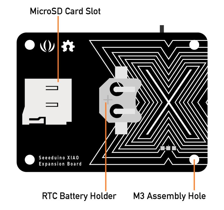
■SDカード情報取得
XAIO拡張ボードのSD Cardスロットに、SDカードを挿して、保存されているファイル情報を取得してみます。
| RasPi | - | QT Py | - | XIAO Expansion Board |
|---|
| | | 3V3 | - | 3V3 |
| | | A2[9] | - | SD CS |
| | | MOSI[35] | - | SDI(MOSI) |
| | | SCK[36] | - | SCK |
| | | MISO[37] | - | SDO(MISO) |
| | | GND | - | GND |
| TX[8] | - | RX[16] | | |
| RX[10] | - | TX[5] | | |
XIAO拡張ボード・SDカードスロットのチップセレクトはA2ピンに割り当てられています。
$ vi src/listfiles.ino
#include <Wire.h>
#include <SPI.h>
#include <SD.h>
#include <SoftwareSerial.h>
SoftwareSerial mySerial(16, 5); // RX, TX

File root;

#define SPI_miso 37
#define SPI_mosi 35
#define SPI_sck  36
#define SPI_sd_ss 9

void setup()
{
  // Open serial communications and wait for port to open:
  mySerial.begin(57600);
   while (!mySerial) {
    ; // wait for serial port to connect. Needed for Leonardo only
  }


  mySerial.print("Initializing SD card...");
  // On the Ethernet Shield, CS is pin 4. It's set as an output by default.
  // Note that even if it's not used as the CS pin, the hardware SS pin
  // (10 on Arduino Uno boards, 53 on the Mega) must be left as an output
  // or the SD library functions will not work.
  // pinMode(SS, OUTPUT);

  SPIClass SDSPI(HSPI);

  SDSPI.begin(SPI_sck, SPI_miso, SPI_mosi, -1);
  pinMode(SPI_sd_ss, OUTPUT);

  if (!SD.begin(SPI_sd_ss, SDSPI)) {
    mySerial.println("initialization failed!");
    return;
  }
  mySerial.println("initialization done.");

  root = SD.open("/");

  printDirectory(root, 0);

  mySerial.println("done!");
}

void loop()
{
  // nothing happens after setup finishes.
}

void printDirectory(File dir, int numTabs) {
  // Begin at the start of the directory
  dir.rewindDirectory();

  while(true) {
     File entry =  dir.openNextFile();
     if (! entry) {
       // no more files
       //mySerial.println("**nomorefiles**");
       break;
     }
     for (uint8_t i=0; i<numTabs; i++) {
       mySerial.print('\t');   // we'll have a nice indentation
     }
     // Print the 8.3 name
     mySerial.print(entry.name());
     // Recurse for directories, otherwise print the file size
     if (entry.isDirectory()) {
       mySerial.println("/");
       printDirectory(entry, numTabs+1);
     } else {
       // files have sizes, directories do not
       mySerial.print("\t\t");
       mySerial.println(entry.size(), DEC);
     }
     entry.close();
   }
}
$ pio run -t upload -e adafruit_qtpy_esp32s2
$ pio device monitor -p /dev/ttyAMA0 -b 57600
Initializing SD card...initialization done.
System Volume Information/
        IndexerVolumeGuid               76
        WPSettings.dat          12
ThreshBinary.tga                230418
AvePooling.tga          230418
Chchange.tga            230418
GrayScale.tga           230418
interface_noise_black.jpg               10368
ReverseColor.tga                230418

done!
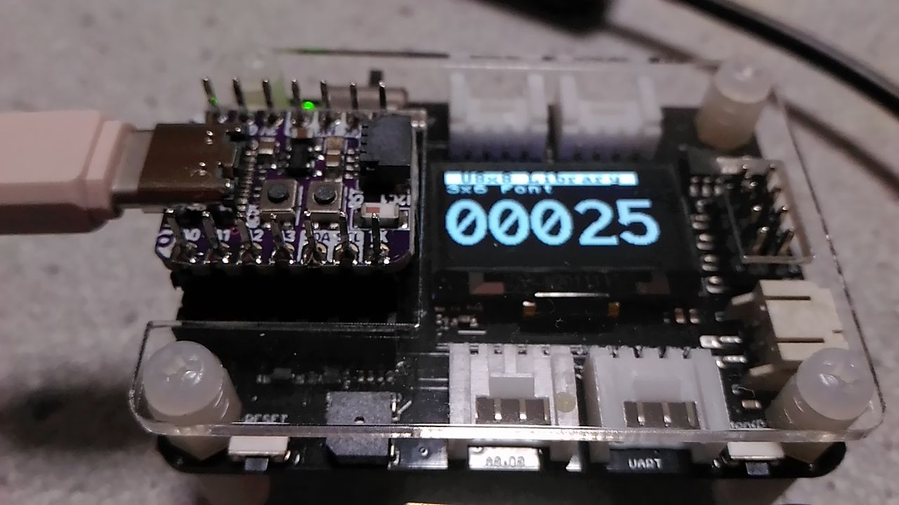
■OLED Display
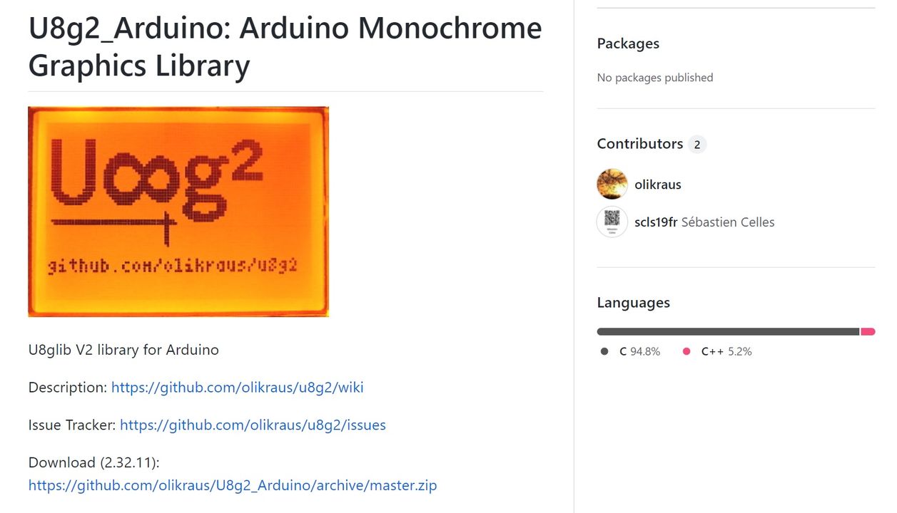
u8g2 ライブラリのインストール
Download (2.32.10): https://github.com/olikraus/U8g2_Arduino/archive/master.zip
U8g2_Arduino-master.zip を解凍して、
・<clib>ディレクトリ
・U8g2lib.cpp
・U8g2lib.h
・U8x8lib.cpp
・U8x8lib.h
をプロジェクトのsrcディレクトリにコピーします。
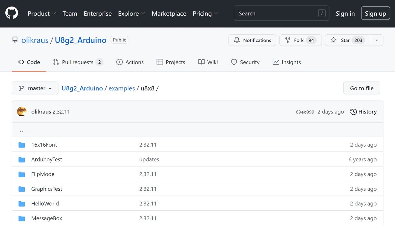
GraphicsTestディレクトリにある、GraphicsTest.ino をプロジェクトのsrcディレクトリにコピーして使用します。
$ vi src/GraphicsTest.ino
#include <Arduino.h>
#include <U8x8lib.h>
#include <Wire.h>

U8X8_SSD1306_128X64_NONAME_SW_I2C u8x8(/* clock=*/ SCL, /* data=*/ SDA, /* reset=*/ U8X8_PIN_NONE);   // OLEDs without Reset of the Display

void setup(void)
{
  u8x8.begin();
}

void pre(void)
{
  u8x8.setFont(u8x8_font_amstrad_cpc_extended_f);
  u8x8.clear();

  u8x8.inverse();
  u8x8.print(" U8x8 Library ");
  u8x8.setFont(u8x8_font_chroma48medium8_r);
  u8x8.noInverse();
  u8x8.setCursor(0,1);
}

void draw_bar(uint8_t c, uint8_t is_inverse)
{
  uint8_t r;
  u8x8.setInverseFont(is_inverse);
  for( r = 0; r < u8x8.getRows(); r++ )
  {
    u8x8.setCursor(c, r);
    u8x8.print(" ");
  }
}

void draw_ascii_row(uint8_t r, int start)
{
  int a;
  uint8_t c;
  for( c = 0; c < u8x8.getCols(); c++ )
  {
    u8x8.setCursor(c,r);
    a = start + c;
    if ( a <= 255 )
      u8x8.write(a);
  }
}

void loop(void)
{
  int i;
  uint8_t c, r, d;
  pre();
  u8x8.print("github.com/");
  u8x8.setCursor(0,2);
  u8x8.print("olikraus/u8g2");
  delay(2000);
  u8x8.setCursor(0,3);
  u8x8.print("Tile size:");
  u8x8.print((int)u8x8.getCols());
  u8x8.print("x");
  u8x8.print((int)u8x8.getRows());

  delay(2000);

  pre();
  for( i = 19; i > 0; i-- )
  {
    u8x8.setCursor(3,2);
    u8x8.print(i);
    u8x8.print("  ");
    delay(150);
  }

  draw_bar(0, 1);
  for( c = 1; c < u8x8.getCols(); c++ )
  {
    draw_bar(c, 1);
    draw_bar(c-1, 0);
    delay(50);
  }
  draw_bar(u8x8.getCols()-1, 0);

  pre();
  u8x8.setFont(u8x8_font_amstrad_cpc_extended_f);
  for( d = 0; d < 8; d ++ )
  {
    for( r = 1; r < u8x8.getRows(); r++ )
    {
      draw_ascii_row(r, (r-1+d)*u8x8.getCols() + 32);
    }
    delay(400);
  }

  draw_bar(u8x8.getCols()-1, 1);
  for( c = u8x8.getCols()-1; c > 0; c--)
  {
    draw_bar(c-1, 1);
    draw_bar(c, 0);
    delay(50);
  }
  draw_bar(0, 0);

  pre();
  u8x8.drawString(0, 2, "Small");
  u8x8.draw2x2String(0, 5, "Scale Up");
  delay(3000);

  pre();
  u8x8.drawString(0, 2, "Small");
  u8x8.setFont(u8x8_font_px437wyse700b_2x2_r);
  u8x8.drawString(0, 5, "2x2 Font");
  delay(3000);

  pre();
  u8x8.drawString(0, 1, "3x6 Font");
  u8x8.setFont(u8x8_font_inb33_3x6_n);
  for(i = 0; i < 100; i++ )
  {
    u8x8.setCursor(0, 2);
    u8x8.print(i);			// Arduino Print function
    delay(10);
  }
  for(i = 0; i < 100; i++ )
  {
    u8x8.drawString(0, 2, u8x8_u16toa(i, 5));	// U8g2 Build-In functions
    delay(10);
  }

  pre();
  u8x8.drawString(0, 2, "Weather");
  u8x8.setFont(u8x8_font_open_iconic_weather_4x4);
  for(c = 0; c < 6; c++ )
  {
    u8x8.drawGlyph(0, 4, '@'+c);
    delay(300);
  }


  pre();
  u8x8.print("print \\n\n");
  delay(500);
  u8x8.println("println");
  delay(500);
  u8x8.println("done");
  delay(1500);

  pre();
  u8x8.fillDisplay();
  for( r = 0; r < u8x8.getRows(); r++ )
  {
    u8x8.clearLine(r);
    delay(100);
  }
  delay(1000);

}
$ pio run -t upload -e adafruit_qtpy_esp32s2
U8g2 ライブラリは多くのディスプレイに対応しているので、便利かもしれません。
Ref.olikraus/U8g2_Arduino
■Buzzer
Seeeduino XIAO Expansion board のサンプルプログラムを動かしてみます。
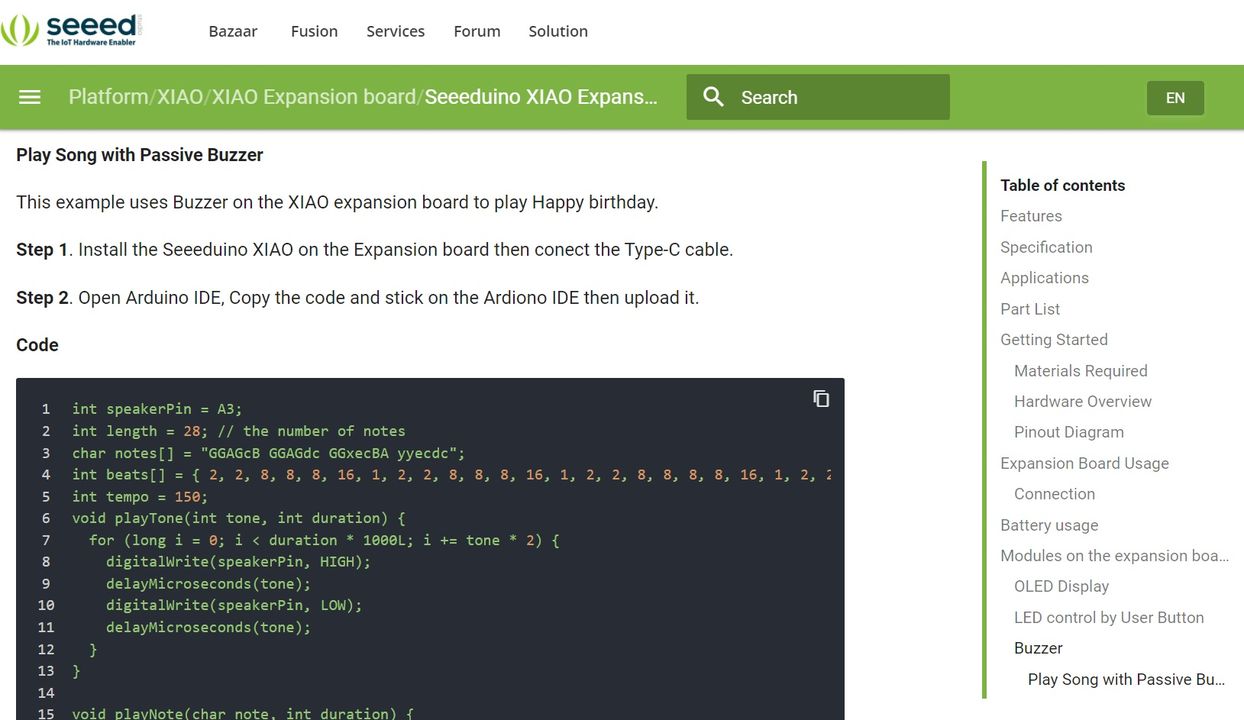
ちょっとだけプログラムを書き換えています。
int speakerPin = A3;
int length = 28; // the number of notes
char notes[] = "GGAGcB GGAGdc GGxecBA yyecdc";
int beats[] = { 2, 2, 8, 8, 8, 16, 1, 2, 2, 8, 8, 8, 16, 1, 2, 2, 8, 8, 8, 8, 16, 1, 2, 2, 8, 8, 8, 16 };
char names[] = {'C', 'D', 'E', 'F', 'G', 'A', 'B', 'c', 'd', 'e', 'f', 'g', 'a', 'b', 'x', 'y'};
int tones[] = { 1915, 1700, 1519, 1432, 1275, 1136, 1014, 956,  834,  765,  593,  468,  346,  224, 655 , 715 };
int tempo = 150;

void playTone(int tone, int duration) {
	for (long i = 0; i < duration * 1000L; i += tone * 2) {
		digitalWrite(speakerPin, HIGH);
		delayMicroseconds(tone);
		digitalWrite(speakerPin, LOW);
		delayMicroseconds(tone);
	}
}

void playNote(char note, int duration) {
	int SPEE = 5;
	for (int i = 0; i < 16; i++) {
		if (names[i] == note) {
			int newduration = duration / SPEE;
			playTone(tones[i], newduration);
		}
	}
}

void setup() {

	pinMode(speakerPin, OUTPUT);

	for (int i = 0; i < length; i++) {
		if (notes[i] == ' ') {
			delay(beats[i] * tempo); // rest
		} else {
			playNote(notes[i], beats[i] * tempo);
		}
		// pause between notes
		delay(tempo);
	}
}

void loop() {}
■Button(D1)
D1 は、pins_arduino.h に定義されていません。QT Py ESP32-S2 の GPIO17 に対応しています。
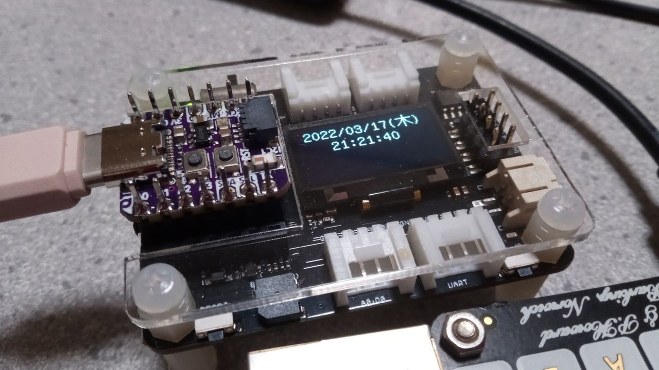
■RTC PCF8563T/5
PCF8563ライブラリをダウンロードして、プロジェクトのsrcディレクトリに配置します。
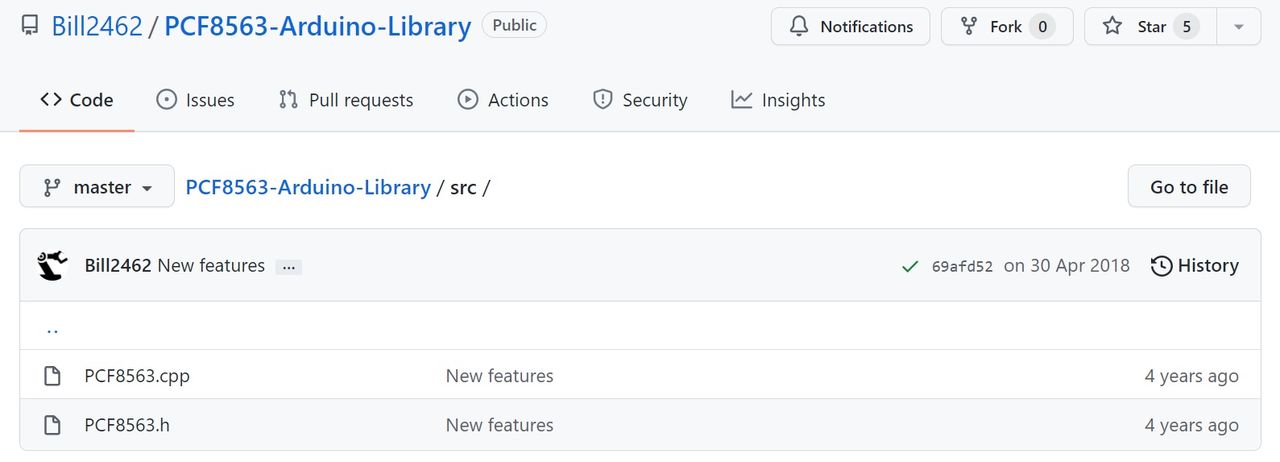
Ref.https://github.com/Bill2462/PCF8563-Arduino-Library
実装には「きむ茶工房ガレージハウス」さんのコードを引用しています。拡張性のあるソースコードです。
#include <U8g2lib.h>
#include <PCF8563.h>

// RTC(PCF8563)を使用する為のコンストラクタ
PCF8563 rtc ;
// SSD1306をグラフィックディスプレイとして使用する為のコンストラクタ
// メモリバッファ(RAM)は1ページ分の128b分確保
// ローテーション(画面回転)なし、SCL=5番ピン SDA=4番ピン
U8G2_SSD1306_128X64_NONAME_1_HW_I2C u8g2(U8G2_R0,SCL,SDA) ;

#define PCF8563_address  0x51 // PCF8563のI2Cアドレス
#define PCF8563_Weekdays 0x06 // 曜日をセットするレジスタアドレス値
// PCF8563に曜日を設定する(0:日曜~6:土曜)
void SetWeekdays(uint8_t wdays) {
  const uint8_t data = (((wdays/10) << 4)|(wdays%10));
  Wire.beginTransmission(PCF8563_address);
  Wire.write(PCF8563_Weekdays);
  Wire.write(data);
  Wire.endTransmission();
}
char WeekDayData[7][4] = {"日","月","火","水","木","金","土"} ;

void setup() {
  u8g2.begin() ;    // OLEDの初期化
  u8g2.enableUTF8Print() ; // Arduino print()関数のUTF8サポートを有効にする

  rtc.init() ;      // RTCの初期化
  // 2021年1月23日 土曜日 15時24分00秒で初期設定
  rtc.stopClock() ; // RTCのカウントを止める
  rtc.setYear(22) ; // 年の設定(00-99)
  rtc.setMonth(3) ; // 月の設定(01-12)
  rtc.setDay(17) ;  // 日の設定(01-31)
  SetWeekdays(4) ;  // 土曜日の設定(0-6)
  rtc.setHour(21) ; // 時の設定(00-23)
  rtc.setMinut(18) ;// 分の設定(00-59)
  rtc.setSecond(0) ;// 秒の設定(00-59)
  rtc.startClock() ;// RTCのカウントを開始する
}
void loop() {
  char buf[12] ;

  Time nowTime = rtc.getTime() ; // 現在の時刻を得る
  u8g2.setFont(u8g2_font_b16_t_japanese2) ; // 日本語フォント高さ16bit

  u8g2.firstPage() ;
  do {
    // 日付の表示
    u8g2.setCursor(7, 16) ;
    sprintf(buf,"%d/%02d/%02d",nowTime.year+2000,nowTime.month,nowTime.day) ;
    u8g2.print(buf) ;
    // 曜日の表示
    u8g2.setCursor(87, 16) ;
    sprintf(buf,"(%s)",WeekDayData[nowTime.weekday]) ;
    u8g2.print(buf) ;
    // 時刻の表示
    u8g2.setCursor(30, 32) ;
    sprintf(buf,"%02d:%02d:%02d",nowTime.hour,nowTime.minute,nowTime.second) ;
    u8g2.print(buf) ;
  } while ( u8g2.nextPage() ) ;

  delay(500) ;
}
Ref.きむ茶工房ガレージハウス 機能拡張ボードをArduinoIDEで開発(SD/RTC編)
■参考文献
・PlatformIOにM5Stamp Picoのボード定義を追加してみた
|
 Raspberry Pi(ラズベリー パイ)は、ARMプロセッサを搭載したシングルボードコンピュータ。イギリスのラズベリーパイ財団によって開発されている。
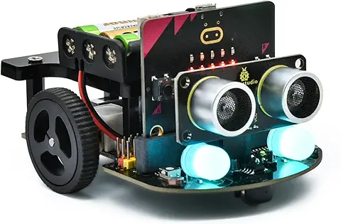 KEYESTUDIO Micro:bit V2ロボットスターターキット (マイクロビットなし) MakecodeとPython用
動き、光と音の使い方、障害物の検知と回避方法、線をたどり、IRリモコンとアプリでコントロールする方法を学びます。
 Maqueen Lite V5 micro:bit ロボットキット STEM用(ライントレース&障害物回避)
Maqueen Lite V5 STEMロボットは、事前調整済みのライントレースアルゴリズム、耐衝撃モーター、開封即使用可能な設計で、ストレスを解消します。
 たいていのことは100日あれば、うまくいく。長田英知著
「時間がなくて、なかなか自分のやりたいことができない」
「一念発起して何かを始めても、いつも三日坊主で終わってしまう」
「色んなことを先延ばしにしたまま、時間だけが過ぎていく」
そこで本書では、そんな著者が独自に開発した、
まったく新しい目標達成メソッド「100日デザイン」について、
その知識と技術を、余すところなくご紹介します。
 まんがで納得ナポレオン・ヒル 思考は現実化する
OLとして雑務をこなす日々に飽き足らず、科学者だった父が残した薬品を商品化すべく、起業を決意した内山麻由(27)。彼女はセミナーで知り合った謎の女性からサポートを得ながら、彼女と二人三脚でナポレオン・ヒルの成功哲学を実践し、さまざまな問題を乗り越えていく。
ヒル博士の<ゴールデンルール>に従い、仕事に、恋に全力疾走する彼女の、成功への物語。
 今日は人生最悪で最高の日 1秒で世界を変えるたったひとつの方法 ひすいこたろう著
偉人の伝記を読むと、最悪な日は、不幸な日ではなく、新しい自分が始まる日であることがわかります。最悪な出来事は、自分の人生が、想像を超えて面白くなる兆しなのです。偉人伝を読むことで、このときの不幸があったおかげで、未来にこういう幸せがくるのかと、人生を俯瞰する視線が立ち上がるのです。
 ご飯は私を裏切らない heisoku著
辛い現実から目を背けて食べるご飯は、いつも美味しく幸せを届けてくれる。
29歳、中卒、恋人いない歴イコール年齢。バイト以外の職歴もなく、短期バイトを転々とする日々。ぐるぐると思索に耽るけど、ご飯を食べると幸せになれる。奇才の新鋭・heisokuが贈るリアル労働グルメ物語!
 【最新版Gemini 3に対応!】できるGemini (できるシリーズ)
Geminiを「最強の知的生産パートナー」として使いこなすための、実践的なノウハウを凝縮した一冊です。
基本的な操作方法から、具体的なビジネスシーンでの活用、日々の業務を自動化するGoogle Workspaceとの連携、さらには自分だけのオリジナルAIを作成する方法まで余すところなく解説します。
 Rustプログラミング完全ガイド 他言語との比較で違いが分かる!
Rustの各手法や考え方を幅広く解説!
500以上のサンプルを掲載。実行結果も確認。
全24章の包括的なチュートリアル。
 ポチらせる文章術
販売サイト・ネット広告・メルマガ・ブログ・ホームページ・SNS…
全WEB媒体で効果バツグン!
カリスマコピーライターが教える「見てもらう」「買ってもらう」「共感してもらう」すべてに効くネット文章術
 小型で便利な Type-C アダプター USB C オス - USB3.1 オスアダプター
Type-C端子のマイコンボードをこのアダプタを介して直接Raspberry Piに挿すことができます。ケーブルなしで便利なツールです。
 Divoom Ditoo Pro ワイヤレススピーカー
15W高音質重低音/青軸キーボード/Bluetooth5.3/ピクセルアート 専用アプリ/USB接続/microSDカード
 電源供給USBケーブル スリム 【5本セット】
USB電源ケーブル 5V DC電源供給ケーブル スリム 【5本セット】 電源供給 バッテリー 修理 自作 DIY 電子工作 (100cm)
|