micro:bit & Pico 拡張ボード

2026.01.29 / 2026.03.07更新
今回は多々あるmicro:bit拡張ボードからお薦め商品のご紹介です
●Keyestudio Micro:bit Smart Robot Car
この micro:bit Smart Robot Car は、micro:bit V2 用です。
とても小さくて、全長10cm,車幅8cm です
micro:bitを熟知されている方は、基本は読み飛ばしてください
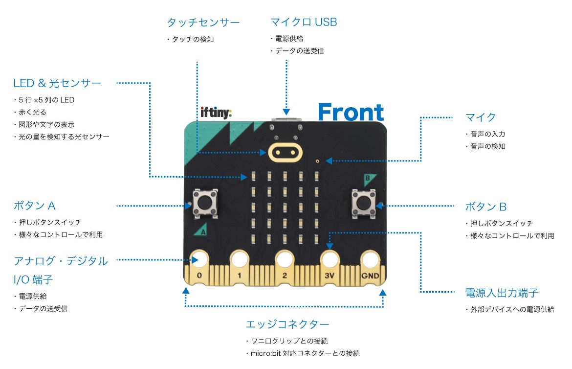
●micro:bit v2.21
これから購入するのであれば、v2.21がお薦めです。
新型のv2.21では性能がかなり向上していて、なにより旧型のv1系とはピンの仕様が異なります。
 マイクロビット (micro:bit) v2のデータシート
Features
○Upgraded processor (nRF52833)
○64MHz Arm Cortex-M4 + FPU (over 4 times faster!)
○512KB Flash storage on board
○128KB RAM
○MEMS Microphone with LED indicator and on-board speaker
○5x5 LED matrix display
○Touch sensitive logo "button"
○Accelerometer/compass (LSM303AGR)
○Light and temperature sensors
○Sleep/off mode for batteries powered projects (w/ LED indicator)
○Up to 200mA of current for external accessories
○Bluetooth 5.0 radio allowing micro:bits to talk to each other
○Notched edge connector (easier to connect things like crocodile clips and conductive thread)
○Dimensions: 52mm x 42mm x 11.7mm
micro:bit v2、Arduino環境でプログラミングに使う端子番号とその機能
| Pxx番号 | 端子機能 | Pxx番号 | 端子機能 |
| 0 | A0, LEFT PAD | 21 | ROW1 |
| 1 | A1, MIDDLE PAD | 22 | ROW2 |
| 2 | A2, RIGHT PAD | 15 | ROW3 |
| 3 | A3, COL3 | 24 | ROW4 |
| 4 | A4, COL1 | 19 | ROW5 |
| 5 | BTN A | 26 | LOGO (touch sensor) |
| 6 | COL4 | 27 | SPEAKER |
| 7 | COL2 | 28 | RUN_MIC |
| 8 | NFC2, GPIO1 | 29 | A6, MIC_IN |
| 9 | NFC1, GPIO2 | 30 | I2C_INT_SDA |
| 10 | A5, COL5 | 31 | I2C_INT_SCL |
| 11 | BTN B | 32 | COMBINED_SENSOR_INT |
| 12 | Accessbility | 33 | RX |
| 13 | SCK | 34 | TX |
| 14 | MISO | | |
| 15 | MOSI | | |
| 16 | GPIO3 | | |
| 17 | 3.3V | | |
| 18 | 3.3V | | |
| 19 | SCL | | |
| 20 | SDA | | |
カードエッジにはP0からP20までの信号が引き出されています。
21番から後はボード上のみでの接続です。
シリアルピンは、(RX,TX) = (33,34) なので、USB端子以外からは接続することはできません。
★ADC (P0(A0),P1(A1),P2(A2))
アナログ‐デジタルコンバータ(ADC)付きGPIO(汎用デジタル入出力)、デフォルトで 10 bit (0~1023) の ADC です。
DAC に使えるピンはありません。
★3V:3ボルト電源入出力
電源出力:microbitがUSBまたはバッテリーで動いている場合、3Vピンを電源出力として使用して周辺機器に電源を供給することができます。
電源入力:microbitがUSBまたはバッテリーで電源供給されていない場合、電源入力として3Vの端子を使ってmicorbitに電源を供給することができます。
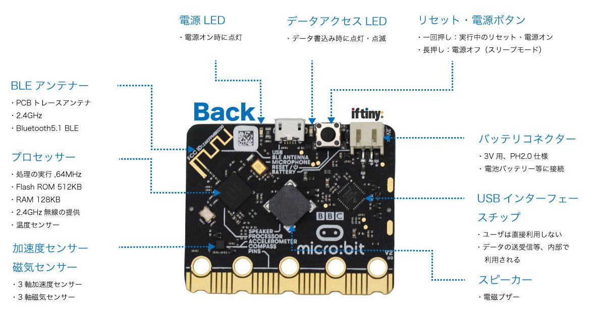
micro:bit v2.21は、Nordic Semiconductor (ノルディック・セミコンダクター) の nRF52833チップ を搭載し、
磁気・加速度センサも LSM 303AGR と実用的な仕様になっています。
micro:bit は学習用デバイスと思っていたのですが、コスパに優れており、nRF52833を搭載していることから、
Arduino IDE や PlatoformIOなどの開発環境を使って、Arduino言語(C言語)による開発が可能です。
●開発環境
ソースコードのビルドには、Raspberry Pi / PlatformIOを使用しています。
Arduino開発環境構築 PlatformIO
$ pio boards micro:bit
Platform: nordicnrf51
=======================================================
ID          MCU      Frequency Flash RAM  Name
----------- -------- --------- ----- ---- -------------
bbcmicrobit NRF51822 16MHz     256KB 16KB BBC micro:bit

Platform: nordicnrf52
===============================================================
ID             MCU      Frequency Flash RAM    Name
-------------- -------- --------- ----- -----  ----------------
bbcmicrobit_v2 NRF52833 64MHz     512KB 128KB  BBC micro:bit V2
ボード情報、ピン定義をを確認しておきます。
$ cat ~/.platformio/platforms/nordicnrf52/boards/bbcmicrobit_v2.json
$ cat ~/.platformio/packages/framework-arduinonordicnrf5/variants/BBCmicrobitV2/variant.h
$ cat ~/.platformio/packages/framework-arduinonordicnrf5/variants/BBCmicrobitV2/variant.cpp
$ pio init -b bbcmicrobit_v2
Tool Manager: Installing platformio/toolchain-gccarmnoneeabi @ >=1.60301.0,<1.80000.0
UnknownPackageError: Could not find the package with 'platformio/toolchain-gccarmnoneeabi @ >=1.60301.0,<1.80000.0' requirements for your system 'linux_aarch64'
toolchain でエラーとなってしまったので、明示的にバージョンを指定しました
$ vi platformio.ini
[env:bbcmicrobit_v2]
platform = nordicnrf52
board = bbcmicrobit_v2
framework = arduino
platform_packages =
        toolchain-gccarmnoneeabi@~1.90301.0
まずは、ボタン操作をしてみます
●1.Bottun A, B
boolean buttonA = false;
boolean buttonB = false;

void setup()
{
	Serial.begin(115200);
	Serial.println("microbit is ready!");
	pinMode(PIN_BUTTON_A, INPUT);
	pinMode(PIN_BUTTON_B, INPUT);
}

void loop()
{
	if ((!digitalRead(PIN_BUTTON_A))&&(!buttonA)) {
		Serial.println("Button A pressed");
		buttonA = true;
	} else {
		buttonA = false;
	}
	if ((!digitalRead(PIN_BUTTON_B))&&(!buttonB)) {
		Serial.println("Button B pressed");
		buttonB = true;
	} else {
		buttonB = false;
	}
	delay(100);
}
$ pio device list
/dev/ttyACM0
------------
Hardware ID: USB VID:PID=0D28:0204 SER=XXXXXX LOCATION=1-1:1.1
Description: BBC micro:bit CMSIS-DAP - mbed Serial Port
/dev/ttyAMA0
------------
Hardware ID: 3f201000.serial
Description: ttyAMA0
$ pio device monitor -p /dev/ttyACM0 -b 115200
A Button!
B Button!
●2.LED MATRIX
5x5のLEDマトリクスはv1.x系にもv2にも存在します。
しかし、v1.x系はROW3端子、COLUMN9端子の非対称な構成で12端子を使って制御、v2系はROW5端子、COLUMN5端子の直交的な配置で10端子で制御です。
LED Matrix
const uint8_t cols[5] = {4, 7, 3, 6, 10};
const uint8_t rows[5] = {21, 22, 23, 24, 25};

void setup() {
	for (int i = 0; i < 5; i++) {
		pinMode(cols[i], OUTPUT);
		digitalWrite(cols[i], HIGH);
	}
	for (int i = 0; i < 5; i++) {
		pinMode(rows[i], OUTPUT);
		digitalWrite(rows[i], LOW);
	}
}

void loop() {
	for (int y = 0; y < 5; y++) {
		for (int x = 0; x < 5; x++) {
			digitalWrite(cols[x], LOW);
			digitalWrite(rows[y], HIGH);
			delay(200);
			digitalWrite(cols[x], HIGH);
			digitalWrite(rows[y], LOW);
		}
	}
}
Adafruit_Microbit ライブラリを使用すると、マトリックスLEDを多彩に制御することができます
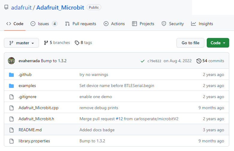
adafruit/Adafruit_Microbit
●I2Cスキャニング
micro:bitは2系統のI2Cを実装していて、オンボードのI2Cを走査するにはWire1を、外部I2C接続にはWireを指定します。
Wire1のピン番号は (SDA,SCL) = (30,31) で、エッジコネクタには引き出されていません。
#include <Wire.h>

void setup()
{
  Wire1.begin();
  Wire1.setClock(400000);    // I2C fast mode, 400kHz

  Serial.begin(115200);
  while (!Serial);             // Leonardo: wait for serial monitor
  Serial.println("\nI2C Scanner");
}

void loop()
{
  byte error, address;
  int nDevices;

  Serial.println("Scanning...");

  nDevices = 0;
  for(address = 1; address < 127; address++ )
  {
    Wire1.beginTransmission(address);
    error = Wire1.endTransmission();

    if (error == 0)
    {
      Serial.print("I2C device found at address 0x");
      if (address<16)
        Serial.print("0");
      Serial.print(address,HEX);
      Serial.println("  !");

      nDevices++;
    }
    else if (error==4)
    {
      Serial.print("Unknown error at address 0x");
      if (address<16)
        Serial.print("0");
      Serial.println(address,HEX);
    }
  }
  if (nDevices == 0)
    Serial.println("No I2C devices found\n");
  else
    Serial.println("done\n");

  delay(5000);
}
$ pio device monitor -p /dev/ttyACM0 -b 115200
Scanning...
I2C device found at address 0x19 !
I2C device found at address 0x1E !
I2C device found at address 0x70 !
I2C device found at address 0x72 !
done
0x19 と 0x1E がオンボード磁気・加速度センサのI2Cアドレスです。
●磁気・加速度センサ LSM 303AGR
・I2C 7-bit addresses 0x19 & 0x1E
・±50 gauss magnetic dynamic range
・1.5 mGauss magnetic sensitivity
・Accelerometer ranges: ±2/±4/±8/±16 g
・As little as 1mg accelerometer sensitivity
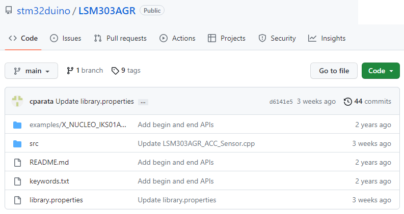
stm32duino/LSM303AGR
gitHubには、LSM303など類似のソースコードがアップされていますが、LSM303AGRを使用しないと正常に動作しません。
srcディレクトリ配下のすべてのソースファイルとexamplesディレクトリのX_NUCLEO_IKS01A2_LSM303AGR_DataLog_Terminal.ino を
PlatformIO の srcディレクトリにコピーします。
※inoファイルとLSM303AGR関連コードを別のフォルダ―に配置するとビルド時にエラーになることがあります。
X_NUCLEO_IKS01A2_LSM303AGR_DataLog_Terminal.ino
line:50
#define DEV_I2C Wire
↓
#define DEV_I2C Wire1
line:60
pinMode(13, OUTPUT); ← 削除
ビルド、micro:bit に書き込み、デバイスモニターで計測結果を表示します。
$ pio device monitor -p /dev/ttyACM0 -b 115200
| Acc[mg]: 12 -974 43 | Mag[mGauss]: -454 132 240 | Temp[C]: 23.00 |
| Acc[mg]: 12 -974 39 | Mag[mGauss]: -462 127 231 | Temp[C]: 22.75 |
| Acc[mg]: 16 -970 47 | Mag[mGauss]: -462 130 243 | Temp[C]: 23.00 |
| Acc[mg]: 12 -974 35 | Mag[mGauss]: -450 135 241 | Temp[C]: 22.75 |
本題は、ここからです
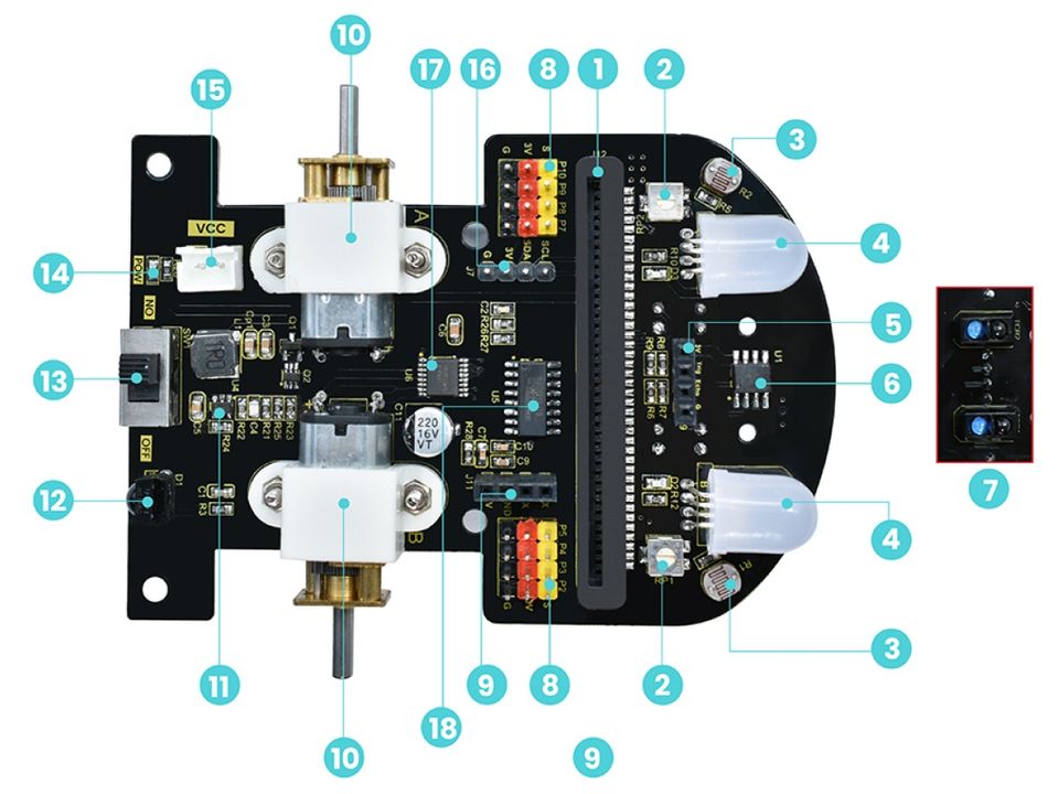
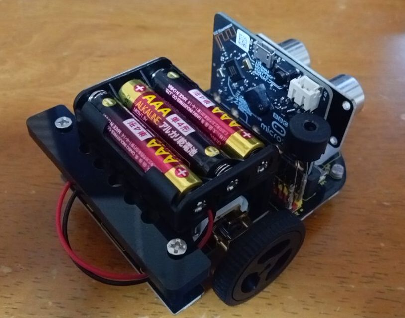
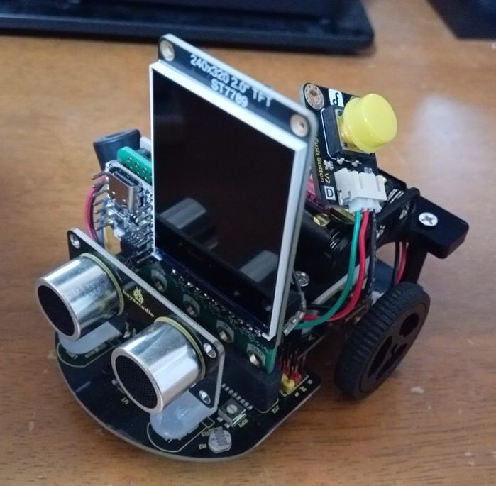
●KEYESTUDIO micro:bit V2ロボット
Dimension:99x78*58mm
| 1 | Slot of Micro:bit board |
| 2 | Potentiometer |
| 3 | Photoresistor |
| 4 | RGB LED |
| 5 | Ultrasonic port |
| 6 | LM393 Voltage comparator |
| 7 | LIne Tracking sensors |
| 8 | IO ports |
| 9 | STC8G1K08 download port |
| 10 | Motor / speed:200RPM |
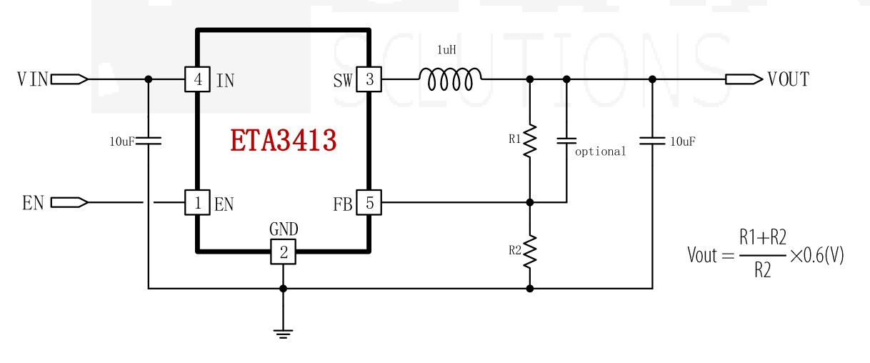
| 11 | ETA3413 drop voltage IC |
| 12 | IR Receiver |
| 13 | Power switch |
| 14 | Power indicator |
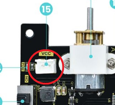
| 15 | External power port / DC 4.5V |
| 16 | I2C extended port |
| 17 | HR8833 motor |
| 18 | STC8G1K08 38I-SOP16 |
Operating voltage of sensors: 3V
Resources
●10.MOTOR
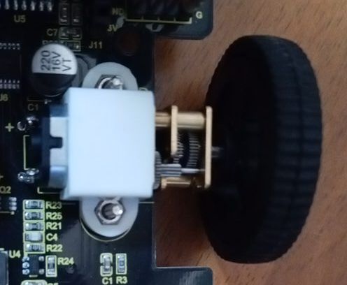
モーターには変速用金属製ギアが取付けられていて、回転数は最大で200RPMになっています
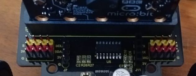
●11.ETA3413 電圧変換
単4乾電池直列電池ボックス4.5Vを3.3Vに降圧します
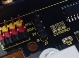
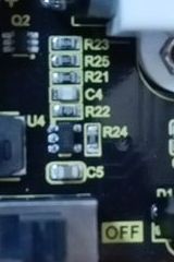 ETA3413周辺の表面実装抵抗
R23: 473 = 47KΩ
R25: 01C = 10KΩ
R21: 01C = 10KΩ
R22: 222 = 2,2KΩ
R24: 01C = 10KΩ
((R22 + R24)/R22)*0.6
= ((2.2 + 10)/2.2)*0.6
= 3.327V
これにより直列乾電池3本の外部電源は
4.5Vから3.3Vに降圧されます
●18.STC8G1K08 / 9.Download Port
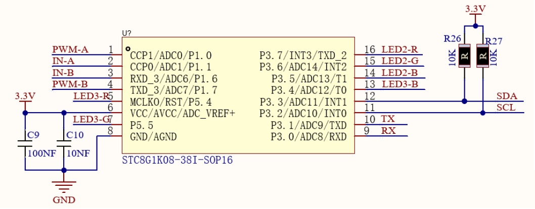
micro:bitはI2Cを介してSTC8G1K08に制御命令を送信し、ST8G1K08はHR8833モーター駆動ICにPWM信号を送信してモーターの回転を制御します。
RGB LEDにもPWM信号を送信します。
STC8G1K08は、8051コアを搭載した8ビットマイコンです。外部水晶振動子が不要で、1.9V~5.5Vの広い電圧範囲で動作します。
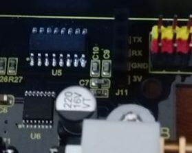
左上の16ピンICがSTC8G1K08、キャパシタを挟んで右にSTC8G1K08へのコード書込み用シリアルポート(TX,RX,GND,3V)が実装されています。
STC8G1K08には既にコードが書き込まれている為、このポートは通常使用しません。
書込み済ファームウェアのコードは公開されていないようです。
●I2Cデバイス・スキャン
STC8G1K08のI2Cアドレスを確認してみます
#include <Wire.h>

void setup()
{
  Wire.begin();
  Wire.setClock(400000);    // I2C fast mode, 400kHz

  Serial.begin(115200);
  while (!Serial);             // Leonardo: wait for serial monitor
  Serial.println("\nI2C Scanner");
}


void loop()
{
  byte error, address;
  int nDevices;

  Serial.println("Scanning...");

  nDevices = 0;
  for(address = 1; address < 127; address++ )
  {
    // The i2c_scanner uses the return value of
    // the Write.endTransmisstion to see if
    // a device did acknowledge to the address.
    Wire.beginTransmission(address);
    error = Wire.endTransmission();

    if (error == 0)
    {
      Serial.print("I2C device found at address 0x");
      if (address<16)
        Serial.print("0");
      Serial.print(address,HEX);
      Serial.println("  !");

      nDevices++;
    }
    else if (error==4)
    {
      Serial.print("Unknown error at address 0x");
      if (address<16)
        Serial.print("0");
      Serial.println(address,HEX);
    }
  }
  if (nDevices == 0)
    Serial.println("No I2C devices found\n");
  else
    Serial.println("done\n");

  delay(5000);           // wait 5 seconds for next scan
}
$ pio device monitor -p /dev/ttyACM0 -b 115200
Scanning...
I2C device found at address 0x30 !
done
0x30 は STC8G1K08 のI2Cアドレスです。
●STC8G1K08制御用クラスライブラリ作成
Keyestudio から提供されている Micro:bit Smart Robot Car用のソースコードはMakeCodeとPythonです。
ざっとコードを眺めてみると主要部分はライブラリに纏められ、ユーザ側記述コードはとてもシンプルです。
しかし美しくありません、制御の実態が分かりにくいので、Arduino言語(C言語)に書き換えました。
ロボットカー用にKEYESTUDIOから提供されているpythonソース・コードを参考にして
STC8G1K08制御用のクラスライブラリを作成しました
STC8G1K08.h
#ifndef __STC8G1K08_H
#define __STC8G1K08_H

#include <Wire.h>

#define STC8G1K08_ADDR  0x30
#define LEFT_MOTOR_INA      0x03
#define LEFT_MOTOR_INB      0x04
#define RIGHT_MOTOR_INA     0x02
#define RIGHT_MOTOR_INB     0x01
#define LEFT_RED_REG        0x08
#define LEFT_GREEN_REG      0x07
#define LEFT_BLUE_REG       0x06
#define RIGHT_RED_REG       0x09
#define RIGHT_GREEN_REG     0x0A
#define RIGHT_BLUE_REG      0x05

class STC8G1K08
{
	private:
		TwoWire  *i2c;
		bool     write(uint8_t addr, uint8_t cmd, uint8_t value);

	public:
		STC8G1K08(TwoWire *wire);
		~STC8G1K08();
		void motor_pwm(int left, int right);
		void led_pwm(long left, long right);
};

#endif /*__STC8G1K08_H*/
STC8G1K08.cpp
#include "STC8G1K08.h"

STC8G1K08::STC8G1K08(TwoWire *wire) {
	i2c = wire;
}

STC8G1K08::~STC8G1K08() {}

bool STC8G1K08::write(uint8_t addr, uint8_t cmd, uint8_t value)
{
	uint8_t error;

	i2c->beginTransmission(addr);
	i2c->write(cmd);
	i2c->write(value);
	error = i2c->endTransmission(1);
	if (error==4) {
		return false;
	} else {
		return true;
	}
}

void STC8G1K08::motor_pwm(int left, int right)
{
	int speed;
	if (left > 0 ) {
		speed = left;
		// left advanced
		write(STC8G1K08_ADDR, LEFT_MOTOR_INA, speed);
		write(STC8G1K08_ADDR, LEFT_MOTOR_INB,     0);
	} else if (left < 0) {
		speed = left * -1;
		// left back
		write(STC8G1K08_ADDR, LEFT_MOTOR_INA,     0);
		write(STC8G1K08_ADDR, LEFT_MOTOR_INB, speed);
	} else {
		// left stop
		write(STC8G1K08_ADDR, LEFT_MOTOR_INA,     0);
		write(STC8G1K08_ADDR, LEFT_MOTOR_INB,     0);
	}

	if (right > 0 ) {
		speed = right;
		// right advanced
		write(STC8G1K08_ADDR, RIGHT_MOTOR_INB,     0);
		write(STC8G1K08_ADDR, RIGHT_MOTOR_INA, speed);
	} else if (right < 0) {
		speed = right * -1;
		// right back
		write(STC8G1K08_ADDR, RIGHT_MOTOR_INB, speed);
		write(STC8G1K08_ADDR, RIGHT_MOTOR_INA,     0);
	} else {
		// right stop
		write(STC8G1K08_ADDR, RIGHT_MOTOR_INB,     0);
		write(STC8G1K08_ADDR, RIGHT_MOTOR_INA,     0);
	}
}

void STC8G1K08::led_pwm(long left, long right)
{
	uint8_t redL, greenL, blueL;
	uint8_t redR, greenR, blueR;

	// LED lights are common anode,
	// 255 is the lowest value and 0 is the brightest value.
	redL   = 255 - ((left  >> 16) & 0xFF);
	greenL = 255 - ((left  >>  8) & 0xFF);
	blueL  = 255 - ((left       ) & 0xFF);
	redR   = 255 - ((right >> 16) & 0xFF);
	greenR = 255 - ((right >>  8) & 0xFF);
	blueR  = 255 - ((right      ) & 0xFF);

	write(STC8G1K08_ADDR, LEFT_RED_REG,    redL  );
	write(STC8G1K08_ADDR, LEFT_GREEN_REG,  greenL);
	write(STC8G1K08_ADDR, LEFT_BLUE_REG,   blueL );
	write(STC8G1K08_ADDR, RIGHT_RED_REG,   redR  );
	write(STC8G1K08_ADDR, RIGHT_GREEN_REG, greenR);
	write(STC8G1K08_ADDR, RIGHT_BLUE_REG,  blueR );
}
●17.HR8833 モータードライバ
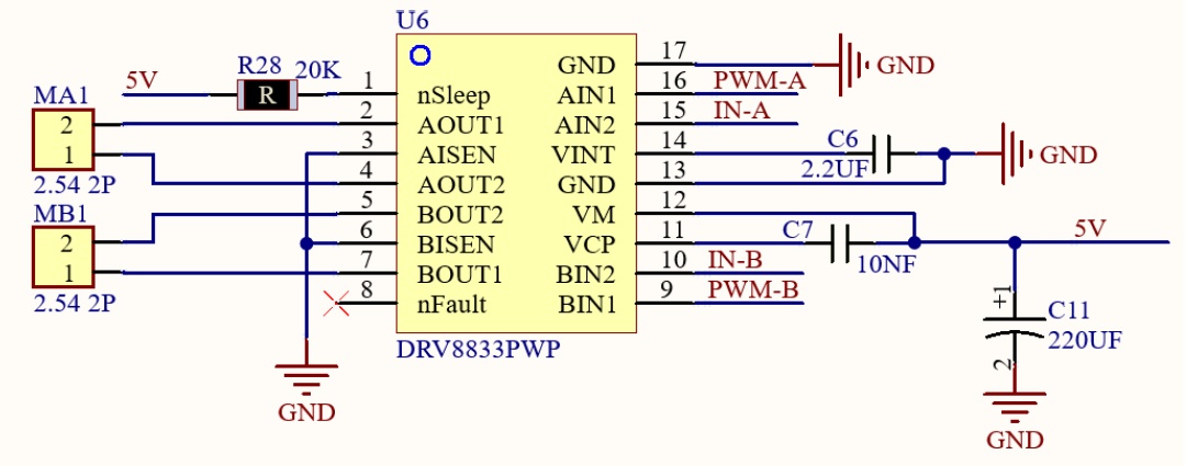
STC8G1K08からのPWM制御信号を受けモーターを回転させます
#include "STC8G1K08.h"
#if defined (ARDUINO_BBC_MICROBIT_V2)
	STC8G1K08 stc8(&Wire);
#elif defined (ARDUINO_ARCH_RP2040)
	STC8G1K08 stc8(&Wire1);
#endif

void setup()
{
#if defined (ARDUINO_BBC_MICROBIT_V2)
	Wire.begin();
#elif defined (ARDUINO_ARCH_RP2040)
	Wire1.setSDA(2);
	Wire1.setSCL(3);
	Wire1.begin();
#endif

	delay(5000);
	stc8.motor_pwm(   0,  0); // stop
	stc8.motor_pwm(  70, 70); // advanced
	delay(1000);
	stc8.motor_pwm( -70,-70); // back
	delay(1000);
	stc8.motor_pwm(  70,-70); // spin left
	delay(1000);
	stc8.motor_pwm( -70, 70); // spin right
	delay(1000);
	stc8.motor_pwm(  70, 30); // turn left
	delay(1000);
	stc8.motor_pwm(  30, 70); // turn right
	delay(1000);
	stc8.motor_pwm(   0,  0); // stop
}

void loop() {}
●4.LED
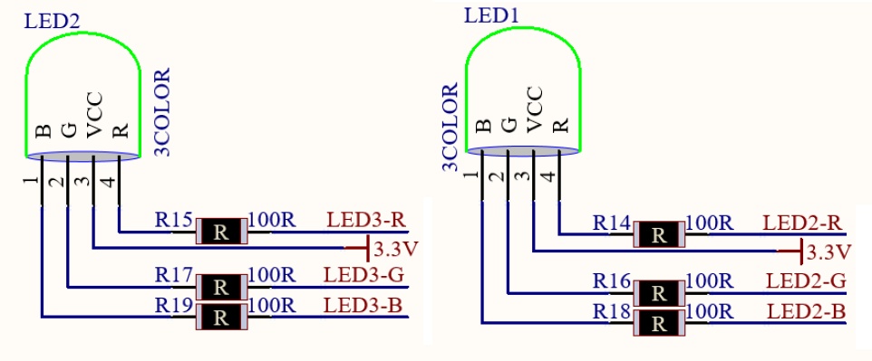
RGB LEDはアノード・コモンなのでRGB値の反転補正が必要です。
STC8G1K08からのPWM制御信号により、RGB LEDを光らせます
#include "STC8G1K08.h"
#if defined (ARDUINO_BBC_MICROBIT_V2)
STC8G1K08 stc8(&Wire);
#elif defined (ARDUINO_ARCH_RP2040)
STC8G1K08 stc8(&Wire1);
#endif
void setup()
{
#if defined (ARDUINO_BBC_MICROBIT_V2)
Wire.begin();
#elif defined (ARDUINO_ARCH_RP2040)
Wire1.setSDA(2);
Wire1.setSCL(3);
Wire1.begin();
#endif
stc8.led_pwm(0,0); // BLACK
}
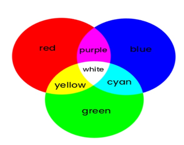
void loop()
{
stc8.led_pwm(0xFF0000,0xFF0000); delay(1000); // RED
stc8.led_pwm(0x00FF00,0x00FF00); delay(1000); // GREEN
stc8.led_pwm(0x0000FF,0x0000FF); delay(1000); // BLUE
stc8.led_pwm(0x00FFFF,0x00FFFF); delay(1000); // CYAN
stc8.led_pwm(0xFF00FF,0xFF00FF); delay(1000); // DARK RED
stc8.led_pwm(0xFFFF00,0xFFFF00); delay(1000); // YELLOW
stc8.led_pwm(0xFFFFFF,0xFFFFFF); delay(1000); // WHITE
}
●3. Photoresistor
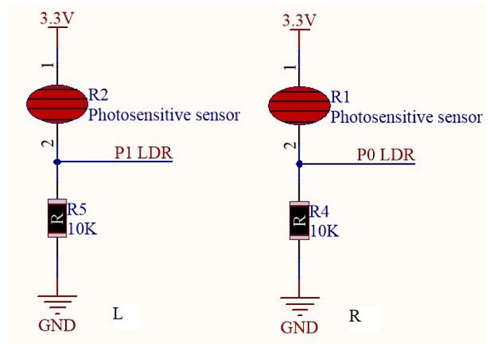
光強度が増加すると抵抗が減少し、アナログポートの電圧が上昇します。
一方、光強度が減少すると抵抗が増加し、アナログポートの電圧が低下します。
この電圧変化を評価してロボットカーを制御します。
下記のコードではロボットカーは光源に向かって走って行きます。
#include "STC8G1K08.h"
#if defined (ARDUINO_BBC_MICROBIT_V2)
	STC8G1K08 stc8(&Wire);
	#define CDS_LEFT_PIN    1
	#define CDS_RIGHT_PIN   0
#elif defined (ARDUINO_ARCH_RP2040)
	STC8G1K08 stc8(&Wire1);
	#define CDS_LEFT_PIN    27
	#define CDS_RIGHT_PIN   26
#endif

unsigned short avgLeft  = 0;
unsigned short avgRight = 0;

unsigned short CDS_L;
unsigned short CDS_R;

void setup()
{
#if defined (ARDUINO_BBC_MICROBIT_V2)
	Wire.begin();
#elif defined (ARDUINO_ARCH_RP2040)
	Wire1.setSDA(2);
	Wire1.setSCL(3);
	Wire1.begin();
#endif

	for (int i = 0; i < 20; i++) {
		avgLeft  += analogRead(CDS_LEFT_PIN);
		avgRight += analogRead(CDS_RIGHT_PIN);
	}
	avgLeft  /= 20;
	avgRight /= 20;
}

void loop()
{
	CDS_L = analogRead(CDS_LEFT_PIN);
	CDS_R = analogRead(CDS_RIGHT_PIN);

	if ((CDS_L >= (avgLeft * 1.2)) && (CDS_R < avgRight)) {
		stc8.motor_pwm(70,-70); // spin left
	} else if ((CDS_L < avgLeft) && (CDS_R >= (avgRight * 1.2))) {
		stc8.motor_pwm(-70,70); // spin right
	} else if ((CDS_L > (avgLeft * 1.2)) && (CDS_R > (avgRight * 1.2))) {
		stc8.motor_pwm(70,70); // advanced
	} else {
		stc8.motor_pwm(0,0); // stop
	}
}
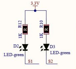
●7. Line Tracking Sensor
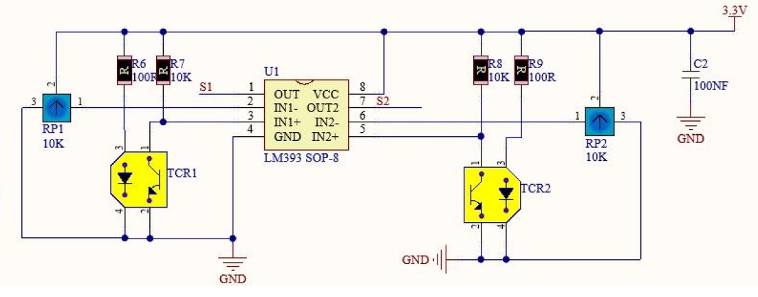
黒線は赤外線信号を吸収し、白い部分は赤外線信号を反射します。
LM393コンパレータは黒線が検知されるとHIGHを、白い部分ではLOWを出力します。
HIGHが出力されると、LED(D2あるいはD3)は消灯し、LOWが出力されると点灯します。
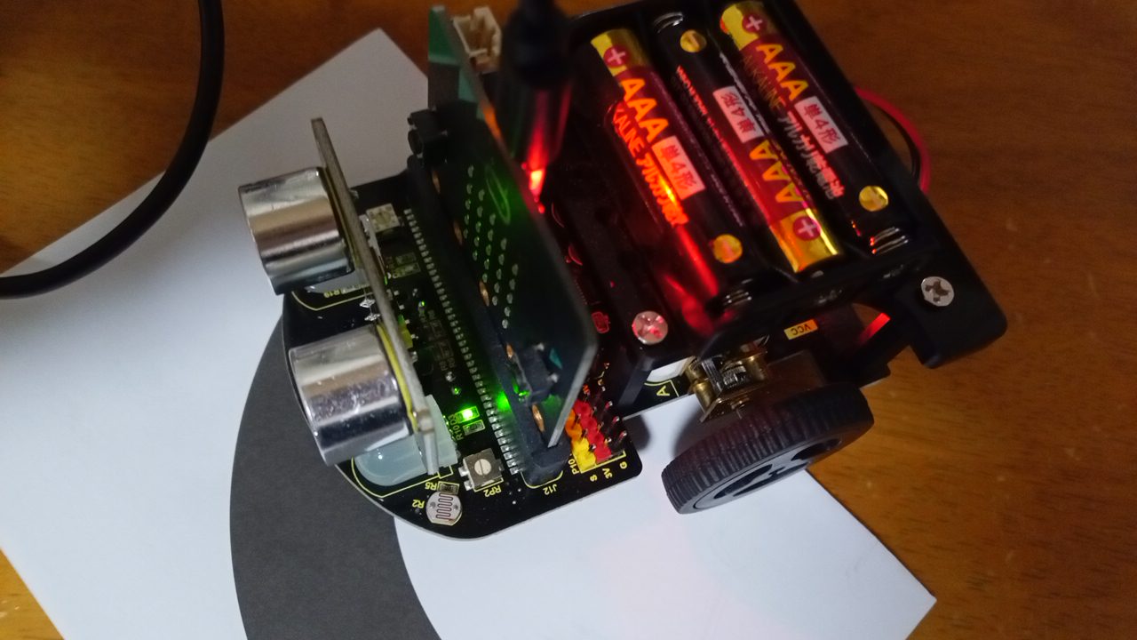
TCRT5000センサが黒線上にあるときに消灯、白紙部分にあるときに点灯するように可変抵抗を回して調整します。
左側のセンサが黒線上にあるので、左側LEDは消灯、右側センサは白紙上にあるので右側LEDは点灯(緑)しています。
#include "STC8G1K08.h"
#if defined (ARDUINO_BBC_MICROBIT_V2)
	STC8G1K08 stc8(&Wire);
	#define TCRT5K_LEFT_PIN  13
	#define TCRT5K_RIGHT_PIN 12
#elif defined (ARDUINO_ARCH_RP2040)
	STC8G1K08 stc8(&Wire1);
	#define TCRT5K_LEFT_PIN  20
	#define TCRT5K_RIGHT_PIN 19
#endif

uint8_t sensor_L;
uint8_t sensor_R;

void setup()
{
#if defined (ARDUINO_BBC_MICROBIT_V2)
	Wire.begin();
#elif defined (ARDUINO_ARCH_RP2040)
	Wire1.setSDA(2);
	Wire1.setSCL(3);
	Wire1.begin();
#endif

	Serial.begin(115200);

	pinMode(TCRT5K_LEFT_PIN,  INPUT_PULLUP);
	pinMode(TCRT5K_RIGHT_PIN, INPUT_PULLUP);
}

void loop()
{
	sensor_L = digitalRead(TCRT5K_LEFT_PIN);
	sensor_R = digitalRead(TCRT5K_RIGHT_PIN);
	Serial.print("sensor_L:");
	Serial.println(sensor_L);
	Serial.print("sensor_R:");
	Serial.println(sensor_R);

	// When both side sensors are on the black line
	if ((sensor_L == 1) && (sensor_R == 1)) {
		stc8.motor_pwm(100,100); // advanced

	// If the right sensor is on the black line and
	// the left sensor is on the white paper, turn right.
	} else if ((sensor_L == 0) && (sensor_R == 1)) {
		stc8.motor_pwm(-100,100); // spin right

	// If the right sensor is on the white paper and
	//  the left sensor is on the black line, turn left.
	} else if ((sensor_L == 1) && (sensor_R == 0)) {
		stc8.motor_pwm(100,-100); // spin left

	// If both side sensors are off the black line
	} else {
		stc8.motor_pwm(   0,  0); // stop
	}
}
LM393
LM393は2つの電圧を比較し、どちらが大きいかを判定してデジタル出力する「電圧コンパレータIC」で、使い方は2つの入力ピン(IN+, IN-)に比較したい電圧を入れ、反転入力(IN-)の電圧が非反転入力(IN+)より高ければ出力がLow(GNDに近い)、IN+が高ければ出力がHigh(VCCに近い)となり、センサーのしきい値検出やアナログ信号のデジタル変換(ADC)に使われます。
電源(VCC/GND)と2つの入力、そして出力(OUT)の基本的な接続で動作し、出力はオープンコレクタのためプルアップ抵抗が必要な場合が多いです。
●5.Ultrasonic Sensor (SRF05)
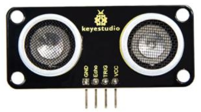
Specifications:
Working voltage: 3-5.5V(DC)
Working current: 50mA/100mA normally is 65mA
Maximum power 0.5W
Maximum detection distance: about 3m
Blind spotless then 4cm
Sensing angle: no more than 15 degrees
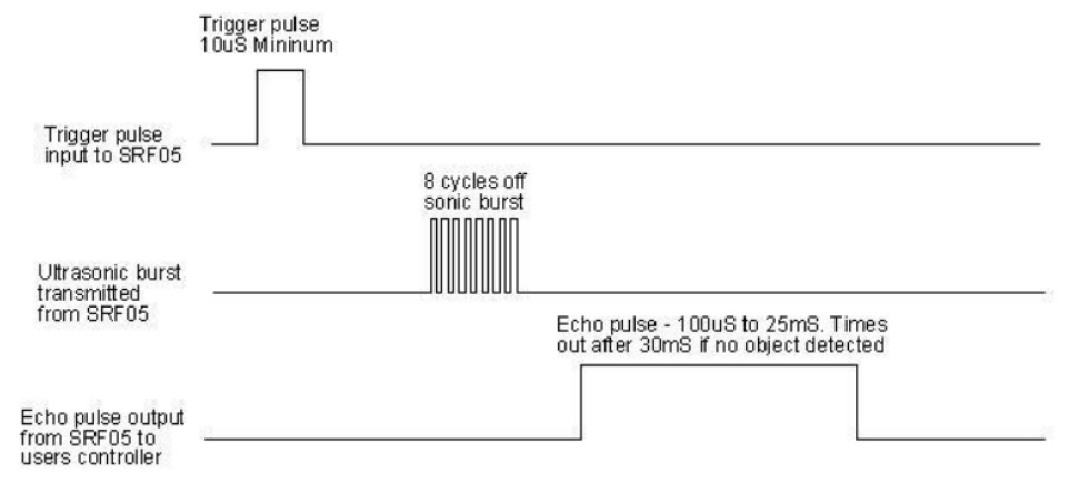
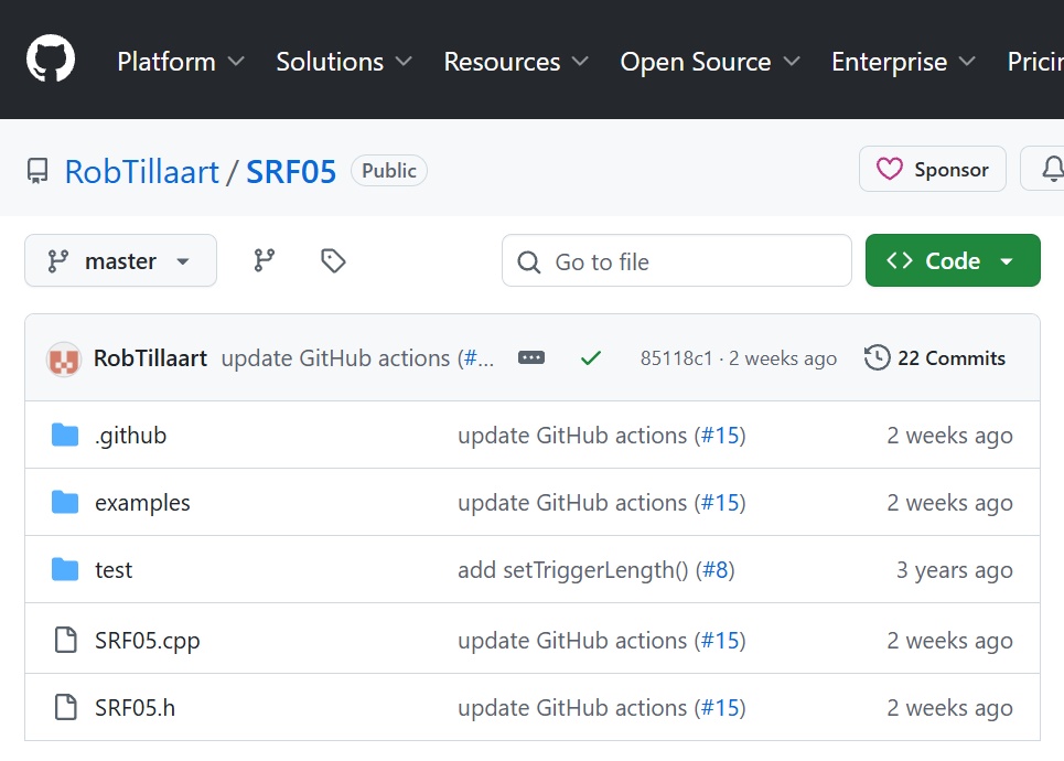
RobTillaart/SRF05
SRF05ライブラリはHC-SR04と互換性があります
下記のコードはロボットカーが前進し、壁から30cmまで接近すると、くるっと左に回り再度前進します。
壁から15㎝まで近づくと後退します。
#include "STC8G1K08.h"
#if defined (ARDUINO_BBC_MICROBIT_V2)
	STC8G1K08 stc8(&Wire);
	#define TRIG_PIN 14
	#define ECHO_PIN 15
#elif defined (ARDUINO_ARCH_RP2040)
	STC8G1K08 stc8(&Wire1);
	#define TRIG_PIN 21
	#define ECHO_PIN 22
#endif

#include "SRF05.h"
SRF05 SRF(TRIG_PIN, ECHO_PIN);

void setup()
{
#if defined (ARDUINO_BBC_MICROBIT_V2)
	Wire.begin();
#elif defined (ARDUINO_ARCH_RP2040)
	Wire1.setSDA(2);
	Wire1.setSCL(3);
	Wire1.begin();
#endif

	Serial.begin(115200);
	SRF.setCorrectionFactor(1.035);
	SRF.setModeAverage(10);
}

int  cm;

void loop()
{
	cm = SRF.getMillimeter() / 10;
  Serial.print(cm);
  Serial.print("cm : ");

	if (cm <= 15) {
		Serial.println("Fall Back");
		stc8.motor_pwm( -70,-70); // back
	} else if ( (cm > 15) && (cm <= 30) ) {
		Serial.println("Spin Left");
		stc8.motor_pwm(  70,-70); // spin left
	} else if ( (cm > 30) && (cm <= 80) ) {
		Serial.println("Go Advanced");
		stc8.motor_pwm(100,100); // advanced
	} else {
		Serial.println("Stop");
		stc8.motor_pwm(0,0); // stop
	}
  delay(100);
}
このコードでは壁に衝突してしまうこともあるので、ロボットカーの速度を調整、
あるいは接近距離による判断基準を変更する必要があります。
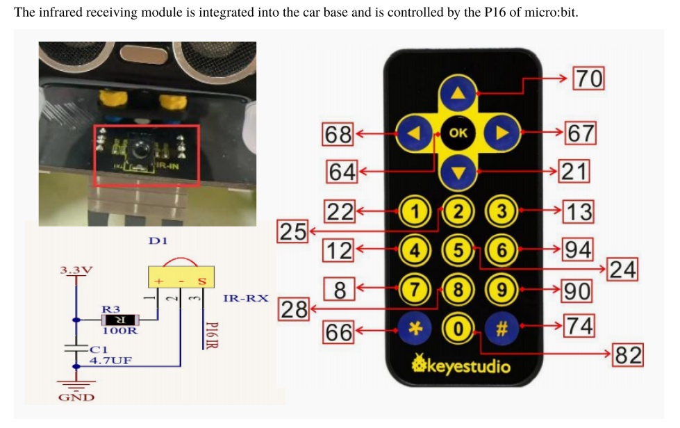
●12.IR Remote Control
Arduino-IRremote/Arduino-IRremote
srcディレクトリ内のコードと、examples/ReceiveDumpのサンプルコードを編集して使います
/examples/ReceiveDump/PinDefinitionsAndMore.h 336行目:
#define IR_RECEIVE_PIN 2
↓
#define IR_RECEIVE_PIN 16
/examples/ReceiveDump/ReceiveDump.ino (全面書換え)
#include "PinDefinitionsAndMore.h"
#include <IRremote.hpp>

void printRawData(uint32_t raw)
{
	for (int step = 16; step >=0; step-=8) {
		uint8_t hex = (raw>>step)&0xFF;
		if (hex & 0xF0) {
			Serial.print(hex>>4, HEX);
		} else {
			Serial.print("0");
		}
		if (hex & 0x0F) {
			Serial.print((hex & 0x0F), HEX);
		} else {
			Serial.print("0");
		}
	}
}

void setup()
{
	Serial.begin(115200);
#if defined (ARDUINO_BBC_MICROBIT_V2)
	IrReceiver.begin(IR_RECEIVE_PIN, ENABLE_LED_FEEDBACK);
#elif defined (ARDUINO_ARCH_RP2040)
	IrReceiver.begin(28, ENABLE_LED_FEEDBACK);
#endif
}

void loop()
{
	uint32_t rawCode, rawData;

	if (IrReceiver.decode()) {  // Grab an IR code
//	IrReceiver.printIRResultShort(&Serial);
		Serial.print(F(" Address=0x"));
		Serial.print(IrReceiver.decodedIRData.address, HEX);
		Serial.print(F(", Command="));
		Serial.print(IrReceiver.decodedIRData.command);
		Serial.print(F(", Raw-Data=0x"));
		rawCode = IrReceiver.decodedIRData.decodedRawData;
		rawData  = (rawCode <<  8) & 0xFF0000;
		rawData |= (rawCode >>  8) & 0x00FF00;
		rawData |= (rawCode >> 24) & 0x0000FF;
		printRawData(rawData);
		Serial.println("");
		delay(50);
		IrReceiver.resume();  // Prepare for the next IR frame
	}
}
$ pio device monitor -p /dev/ttyACM0 -b 115200
Address=0x0, Command=70, Raw-Data=0xFF46B9
Address=0x0, Command=68, Raw-Data=0xFF44BB
Address=0x0, Command=64, Raw-Data=0xFF40BF
Address=0x0, Command=67, Raw-Data=0xFF43BC
Address=0x0, Command=21, Raw-Data=0xFF15EA
Address=0x0, Command=22, Raw-Data=0xFF16E9
Address=0x0, Command=25, Raw-Data=0xFF19E6
Address=0x0, Command=13, Raw-Data=0xFF0DF2
Address=0x0, Command=12, Raw-Data=0xFF0CF3
Address=0x0, Command=24, Raw-Data=0xFF18E7
Address=0x0, Command=94, Raw-Data=0xFF5EA1
Address=0x0, Command=8, Raw-Data=0xFF08F7
Address=0x0, Command=28, Raw-Data=0xFF1CE3
Address=0x0, Command=90, Raw-Data=0xFF5AA5
Address=0x0, Command=66, Raw-Data=0xFF42BD
Address=0x0, Command=82, Raw-Data=0xFF52AD
Address=0x0, Command=74, Raw-Data=0xFF4AB5
リモコンが押されたときに取得されるCommandコードを元にロボットカーを制御することが可能です
●8.IOポート
IOポートは左側 P10,P9,P8,P7、右側 P5,P4,P3,P2 が引き出されています
micro:bit V2 のエッジコネクタ

micro:bit V2ロボットで使用しているポートと空ポートの一覧です
| Pxx番号 | 端子機能 | ROBOT CAR |
| 0 | A0, LEFT PAD | Photoresistor(right) |
| 1 | A1, MIDDLE PAD | Photoresistor(left) |
| 2 | A2, RIGHT PAD | P2 |
| 3 | A3, COL3 | P3 |
| 4 | A4, COL1 | P4 |
| 5 | BTN A | P5 |
| 6 | COL4 | |
| 7 | COL2 | P7 |
| 8 | NFC2, GPIO1 | P8 |
| 9 | NFC1, GPIO2 | P9 |
| 10 | A5, COL5 | P10 |
| 11 | BTN B | |
| 12 | Accessbility | TCRT5K(right) |
| 13 | SCK | TCRT5K(left) |
| 14 | MISO | TRIG |
| 15 | MOSI | ECHO |
| 16 | GPIO3 | IR Receiver |
| 17 | 3.3V | |
| 18 | 3.3V | |
| 19 | SCL | STC8G1K08 |
| 20 | SDA | STC8G1K08 |
赤文字にある8つのポートが使用可能です
●16.I2C拡張ポート
I2Cソケットも実装されているので、空ポートも合わせると十分拡張ボードとして使用できます
●ブザー
Arduino言語でオンボード・ブザーを制御できなかったので、外付けで圧電スピーカーをP2に取り付けました
// The micro:bit v2 has a speaker connected to pin 0
#if defined (ARDUINO_BBC_MICROBIT_V2)
	#define PIN_BUZZER    2
	#define PIN_PUSH_BTN  PIN_BUTTON_A
#elif defined (ARDUINO_ARCH_RP2040)
	#define PIN_BUZZER    6
	#define PIN_PUSH_BTN  11
#endif

void setup()
{
	pinMode(PIN_BUZZER,   OUTPUT);
#if defined (ARDUINO_BBC_MICROBIT_V2)
	pinMode(PIN_PUSH_BTN, INPUT_PULLUP);
#elif defined (ARDUINO_ARCH_RP2040)
	pinMode(PIN_PUSH_BTN, INPUT);
#endif
}

void beep(int hz, int ms)
{
	long loop = (ms / 1000) * hz;
	long us = 500000 / hz;
	// tone(SPEAKER_PIN, 262, 1000);
	// 1000Hz (Period 1ms = 1000us) -> HIGH 500us, LOW 500us
	for (long lng = 0; lng < loop; lng++) {
		digitalWrite(PIN_BUZZER, HIGH);
		delayMicroseconds(us);
		digitalWrite(PIN_BUZZER, LOW);
		delayMicroseconds(us);
	}
}

void loop() {
  // When button A is pressed, LOW is output.
#if defined (ARDUINO_BBC_MICROBIT_V2)
  if (digitalRead(PIN_PUSH_BTN) == LOW) {
#elif defined (ARDUINO_ARCH_RP2040)
  if (digitalRead(PIN_PUSH_BTN) == HIGH) {
#endif
		beep(262,1000); // Play a 262Hz C note for 1000ms
		beep(440,1000); // Play a 440Hz A note for 1000ms
  }
}
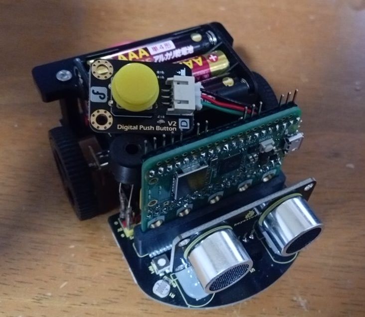
後述の Raspberry Pi Pico では、外付けのプッシュボタンを取付けています。
このプッシュボタン・モジュールにはプルダウン回路が内蔵されています。
●補足:STC8G1K08プログラミング
$ pio boards STC8G1K08
Platform: intel_mcs51
===============================================================
ID         MCU        Frequency Flash RAM    Name
---------- ---------- --------- ----- ------ ------------------
STC8G1K08  STC8G1K08  11MHz     8KB   1.25KB Generic STC8G1K08
STC8G1K08A STC8G1K08A 11MHz     8KB   1.25KB Generic STC8G1K08A
STC8G1K08T STC8G1K08T 11MHz     8KB   1.25KB Generic STC8G1K08T
$ pio init -b STC8G1K08
Platform Manager: Installing intel_mcs51
Downloading [####################################] 100%
Unpacking [####################################] 100%
Platform Manager: intel_mcs51@2.2.0 has been installed!
Tool Manager: Installing platformio/toolchain-sdcc @ >=1.40100.0,<1.40401.0
UnknownPackageError: Could not find the package with 'platformio/toolchain-sdcc @ >=1.40100.0,<1.40401.0' requirements for your system 'linux_aarch64'
$ cat .platformio/platforms/intel_mcs51/boards/STC8G1K08.json
{
  "build": {
    "core": "naked",
    "extra_flags": "-DSTC8G1KXX -DSTC8G1K08 -DNAKED_ARCH_MCS51 -DNAKED_MCS51_STC8G1KXX",
    "f_cpu": "11059200L",
    "size_iram": 256,
    "size_xram": 1024,
    "size_code": 8192,
    "size_heap": 128,
    "mcu": "stc8g1k08",
    "cpu": "mcs51",
    "variant": "stc8g1kxx"
  },
  "frameworks": [],
  "upload": {
    "maximum_ram_size": 1280,
    "maximum_size": 8192,
    "protocol": "stcgal",
    "stcgal_protocol": "stc8",
    "protocols": [
      "stcgal"
    ]
  },
  "name": "Generic STC8G1K08",
  "url": "http://www.stcmicro.com/stc/stc8g1k08.html",
  "vendor": "STC"
}
急ぎではないので、放置します。STC8G1K08を使う機会があればそのときに検討します。
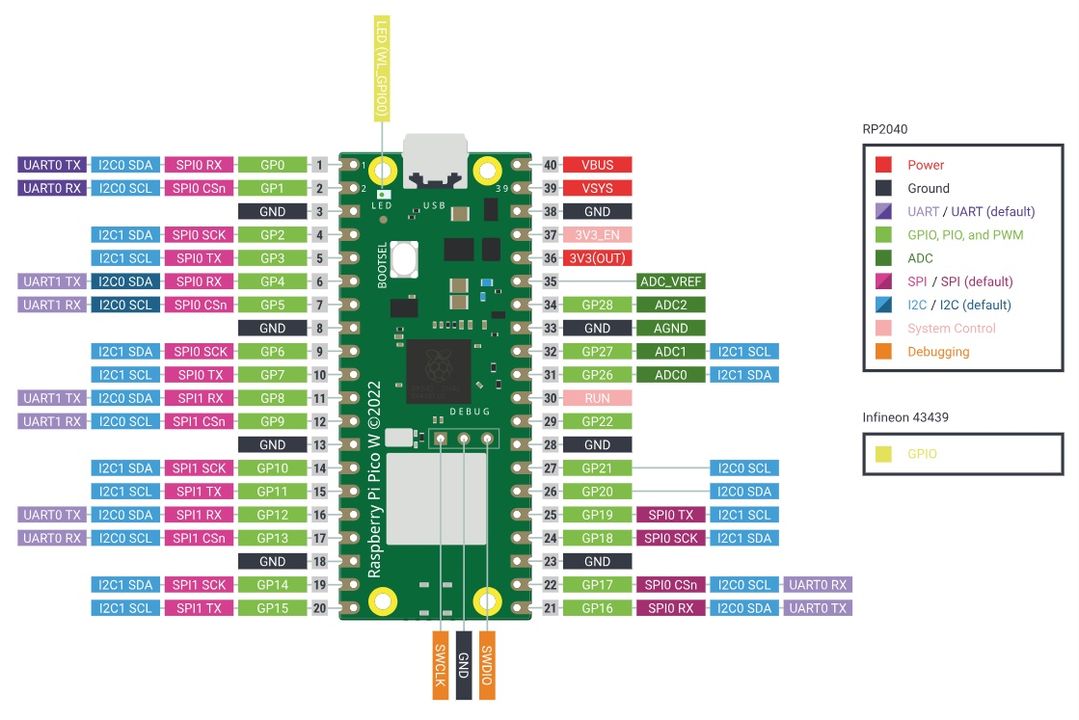
●Micro:bit Smart Robot Car を Raspberry Pi Pico で制御する
このロボットカーではSPI端子がライントラッキングセンサーと超音波センサーに利用されてしまっています。
そこでSPIを利用したい場合は、micro:bit を Raspberry Pi Pico に差し替えて利用します。
Raspberr Pi Pico W Pinouts
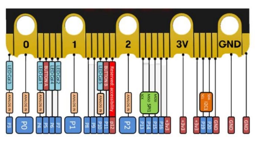
Picoの端子を、micro:bit V2のエッジコネクタに対応させます
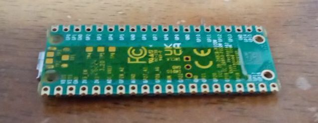
Pico の裏側のパッドなどがショートしないようにポリイミドテープで絶縁しています。
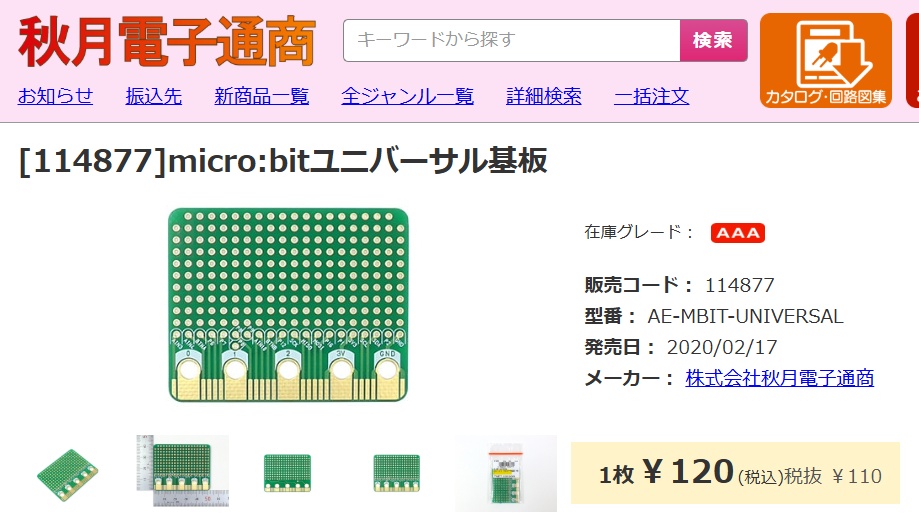
秋月電子が販売しているmicro:bitユニバーサル基板の横方向スルーホール数はPicoのピン数と同じです
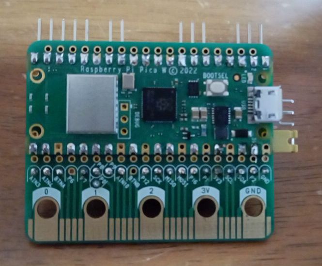
上部はユニバーサル基板にL型ヘッダーピンを通してPicoにハンダ付けしています。
上部ヘッダーピン   Pico         エッジコネクタ
PIN_SERIAL1_TX ←   1 GP0
PIN_SERIAL1_RX ←   2 GP1
GND            ←  GND
                    4 GP2 PIN_WIRE1_SDA → P20 STC8G1K08
                    5 GP3 PIN_WIRE1_SCL → P19 STC8G1K08
PIN_WIRE0_SDA  ←   6 GP4
PIN_WIRE0_SCL  ←   7 GP5
               ←  GND
                    9 GP6     → P2
                   10 GP7     → P3
                   11 GP8     → P4
                   12 GP9     → P5
              ←   GND
              ←   14 GP10
                   15 GP11    → P7
PIN_SPI1_MISO ←   16 GP12
PIN_SPI1_SS   ←   17 GP13
GND           ←   GND
PIN_SPI1_SCK  ←   19 GP14
PIN_SPI1_MOSI ←   20 GP15
                   21 GP16     → P8
                   22 GP17     → P9
                   GND
                   24 GP18     → P10
                   25 GP19     → P12 TCRT5K(right)
                   26 GP20     → P13 TCRT5K(left)
                   27 GP21     → P14 TRIG
                   GND
                   29 GP22     → P15 ECHO
                   RUN
                   31 GP26     → P0 Photoresistor(right)
                   32 GP27     → P1 Photoresistor(left)
                   GND
                   34 GP28     → P16 IR Receiver
                   VREF
                   3V3(OUT)    → 3V3
                   3V3_EN
                   GND       ←→ GND
                   VSYS        ← 3V3
                   VBUS(5V)
※GP26,27,28は、12bitアナログ端子です
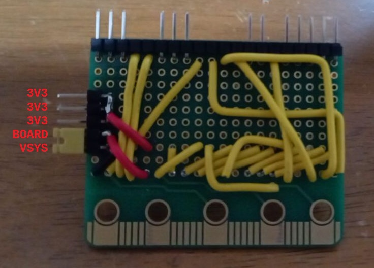
micro:bitの3V端子は入出力として使えますが、Picoの3V3端子は出力専用です。
拡張ボード側から電力供給を受ける場合は、左側ヘッダーピン BOARDとVSYSをショートさせ、
Pico側から拡張ボードへ給電する場合は、BOARDと1つ上の3V3をショートさせます。
プルダウン回路内蔵のプッシュボタンを取り付けています。
●プロジェクトの作成
$ pio boards pico
Platform: raspberrypi
===================================================
ID   MCU    Frequency Flash RAM   Name
---- ------ --------- ----- ----- -----------------
pico RP2040 133MHz    2MB   264KB Raspberry Pi Pico
$ pio init -b pico
Resolving pico dependencies...
Platform Manager: Installing raspberrypi
Downloading [####################################] 100%
Unpacking [####################################] 100%
Platform Manager: raspberrypi@1.18.0 has been installed!
Tool Manager: Installing platformio/toolchain-gccarmnoneeabi @ ~1.90201.0
UnknownPackageError: Could not find the package with 'platformio/toolchain-gccarmnoneeabi @ ~1.90201.0' requirements for your system 'linux_aarch64'
$ vi platformio.ini
[env:pico]
platform = https://github.com/maxgerhardt/platform-raspberrypi.git
board = pico
framework = arduino
board_build.core = earlephilhower
upload_port = /media/pi/RPI-RP2/
monitor_port = /dev/ttyACM0
monitor_speed = 115200
Raspberry Pi Pico W and Pico WH
~/.platformio/platforms/raspberrypi@src-ff76a3915224135aafad379817f41edd/boards/rpipicow.json
{
    "build": {
        "arduino": {
            "earlephilhower": {
                "boot2_source": "boot2_w25q080_2_padded_checksum.S",
                "usb_vid": "0x2E8A",
                "usb_pid": "0xF00A"
            }
        },
        "core": "earlephilhower",
        "cpu": "cortex-m0plus",
        "extra_flags": "-DARDUINO_RASPBERRY_PI_PICO_W -DARDUINO_ARCH_RP2040 -DUSBD_MAX_POWER_MA=250  -DPICO_CYW43_SUPPORTED=1 -DCYW43_PIN_WL_DYNAMIC=1",
        "f_cpu": "133000000L",
        "hwids": [
            [
                "0x2E8A",
                "0x00C0"
            ],
            [
                "0x2E8A",
                "0xF00A"
            ]
        ],
        "mcu": "rp2040",
        "variant": "rpipicow"
    },
    "debug": {
        "jlink_device": "RP2040_M0_0",
        "openocd_target": "rp2040.cfg",
        "svd_path": "rp2040.svd"
    },
    "frameworks": [
        "arduino",
        "picosdk"
    ],
    "name": "Pico W",
    "upload": {
        "maximum_ram_size": 262144,
        "maximum_size": 2097152,
        "require_upload_port": true,
        "native_usb": true,
        "use_1200bps_touch": true,
        "wait_for_upload_port": false,
        "protocol": "picotool",
        "protocols": [
            "blackmagic",
            "cmsis-dap",
            "jlink",
            "raspberrypi-swd",
            "picotool",
            "picoprobe"
        ]
    },
    "url": "https://www.raspberrypi.org/products/raspberry-pi-pico/",
    "vendor": "Raspberry Pi"
~/.platformio/packages/framework-arduinopico/variants/rpipicow/pins_arduino.h
#pragma once

// Pin definitions taken from:
//    https://datasheets.raspberrypi.org/pico/pico-datasheet.pdf

#include

// LEDs
#define PIN_LED        (64u)

// Serial
#define PIN_SERIAL1_TX (0u)
#define PIN_SERIAL1_RX (1u)

#define PIN_SERIAL2_TX (8u)
#define PIN_SERIAL2_RX (9u)

// SPI
#define PIN_SPI0_MISO  (16u)
#define PIN_SPI0_MOSI  (19u)
#define PIN_SPI0_SCK   (18u)
#define PIN_SPI0_SS    (17u)

#define PIN_SPI1_MISO  (12u)
#define PIN_SPI1_MOSI  (15u)
#define PIN_SPI1_SCK   (14u)
#define PIN_SPI1_SS    (13u)

// Wire
#define PIN_WIRE0_SDA  (4u)
#define PIN_WIRE0_SCL  (5u)

#define PIN_WIRE1_SDA  (26u)
#define PIN_WIRE1_SCL  (27u)

#define SERIAL_HOWMANY (3u)
#define SPI_HOWMANY    (2u)
#define WIRE_HOWMANY   (2u)

#include "../generic/common.h"
~/.platformio/packages/framework-arduinopico/variants/generic/common.h
#pragma once

#include

#define PINS_COUNT          (30u)
#define NUM_DIGITAL_PINS    (30u)
#define NUM_ANALOG_INPUTS   (4u)
#define NUM_ANALOG_OUTPUTS  (0u)
#define ADC_RESOLUTION      (12u)
#define WIRE_INTERFACES_COUNT (WIRE_HOWMANY)

#ifdef PIN_LED
#define LED_BUILTIN PIN_LED
#endif

#ifdef __PIN_D0
static const uint8_t D0 = __PIN_D0;
#else
static const uint8_t D0 = (0u);
#endif
#ifdef __PIN_D1
static const uint8_t D1 = __PIN_D1;
#else
static const uint8_t D1 = (1u);
#endif
#ifdef __PIN_D2
static const uint8_t D2 = __PIN_D2;
#else
static const uint8_t D2 = (2u);
#endif
#ifdef __PIN_D3
static const uint8_t D3 = __PIN_D3;
#else
static const uint8_t D3 = (3u);
#endif
#ifdef __PIN_D4
static const uint8_t D4 = __PIN_D4;
#else
static const uint8_t D4 = (4u);
#endif
#ifdef __PIN_D5
static const uint8_t D5 = __PIN_D5;
#else
static const uint8_t D5 = (5u);
#endif
#ifdef __PIN_D6
static const uint8_t D6 = __PIN_D6;
#else
static const uint8_t D6 = (6u);
#endif
#ifdef __PIN_D7
static const uint8_t D7 = __PIN_D7;
#else
static const uint8_t D7 = (7u);
#endif
#ifdef __PIN_D8
static const uint8_t D8 = __PIN_D8;
#else
static const uint8_t D8 = (8u);
#endif
#ifdef __PIN_D9
static const uint8_t D9 = __PIN_D9;
#else
static const uint8_t D9 = (9u);
#endif
#ifdef __PIN_D10
static const uint8_t D10 = __PIN_D10;
#else
static const uint8_t D10 = (10u);
#endif
#ifdef __PIN_D11
static const uint8_t D11 = __PIN_D11;
#else
static const uint8_t D11 = (11u);
#endif
#ifdef __PIN_D12
static const uint8_t D12 = __PIN_D12;
#else
static const uint8_t D12 = (12u);
#endif
#ifdef __PIN_D13
static const uint8_t D13 = __PIN_D13;
#else
static const uint8_t D13 = (13u);
#endif
#ifdef __PIN_D14
static const uint8_t D14 = __PIN_D14;
#else
static const uint8_t D14 = (14u);
#endif
#ifdef __PIN_D15
static const uint8_t D15 = __PIN_D15;
#else
static const uint8_t D15 = (15u);
#endif
#ifdef __PIN_D16
static const uint8_t D16 = __PIN_D16;
#else
static const uint8_t D16 = (16u);
#endif
#ifdef __PIN_D17
static const uint8_t D17 = __PIN_D17;
#else
static const uint8_t D17 = (17u);
#endif
#ifdef __PIN_D18
static const uint8_t D18 = __PIN_D18;
#else
static const uint8_t D18 = (18u);
#endif
#ifdef __PIN_D19
static const uint8_t D19 = __PIN_D19;
#else
static const uint8_t D19 = (19u);
#endif
#ifdef __PIN_D20
static const uint8_t D20 = __PIN_D20;
#else
static const uint8_t D20 = (20u);
#endif
#ifdef __PIN_D21
static const uint8_t D21 = __PIN_D21;
#else
static const uint8_t D21 = (21u);
#endif
#ifdef __PIN_D22
static const uint8_t D22 = __PIN_D22;
#else
static const uint8_t D22 = (22u);
#endif
#ifdef __PIN_D23
static const uint8_t D23 = __PIN_D23;
#else
static const uint8_t D23 = (23u);
#endif
#ifdef __PIN_D24
static const uint8_t D24 = __PIN_D24;
#else
static const uint8_t D24 = (24u);
#endif
#ifdef __PIN_D25
static const uint8_t D25 = __PIN_D25;
#else
static const uint8_t D25 = (25u);
#endif
#ifdef __PIN_D26
static const uint8_t D26 = __PIN_D26;
#else
static const uint8_t D26 = (26u);
#endif
#ifdef __PIN_D27
static const uint8_t D27 = __PIN_D27;
#else
static const uint8_t D27 = (27u);
#endif
#ifdef __PIN_D28
static const uint8_t D28 = __PIN_D28;
#else
static const uint8_t D28 = (28u);
#endif
#ifdef __PIN_D29
static const uint8_t D29 = __PIN_D29;
#else
static const uint8_t D29 = (29u);
#endif

#if defined(PICO_RP2040) || (defined(PICO_RP2350) && PICO_RP2350A)

#ifdef __PIN_A0
static const uint8_t A0 = __PIN_A0;
#else
static const uint8_t A0 = (26u);
#endif

#ifdef __PIN_A1
static const uint8_t A1 = __PIN_A1;
#else
static const uint8_t A1 = (27u);
#endif

#ifdef __PIN_A2
static const uint8_t A2 = __PIN_A2;
#else
static const uint8_t A2 = (28u);
#endif

#ifdef __PIN_A3
static const uint8_t A3 = __PIN_A3;
#else
static const uint8_t A3 = (29u);
#endif

#elif defined(PICO_RP2350) && !PICO_RP2350A // RP2350B

#ifdef __PIN_D30
static const uint8_t D30 = __PIN_D30;
#else
static const uint8_t D30 = (30u);
#endif
#ifdef __PIN_D31
static const uint8_t D31 = __PIN_D31;
#else
static const uint8_t D31 = (31u);
#endif
#ifdef __PIN_D32
static const uint8_t D32 = __PIN_D32;
#else
static const uint8_t D32 = (32u);
#endif
#ifdef __PIN_D33
static const uint8_t D33 = __PIN_D33;
#else
static const uint8_t D33 = (33u);
#endif
#ifdef __PIN_D34
static const uint8_t D34 = __PIN_D34;
#else
static const uint8_t D34 = (34u);
#endif
#ifdef __PIN_D35
static const uint8_t D35 = __PIN_D35;
#else
static const uint8_t D35 = (35u);
#endif
#ifdef __PIN_D36
static const uint8_t D36 = __PIN_D36;
#else
static const uint8_t D36 = (36u);
#endif
#ifdef __PIN_D37
static const uint8_t D37 = __PIN_D37;
#else
static const uint8_t D37 = (37u);
#endif
#ifdef __PIN_D38
static const uint8_t D38 = __PIN_D38;
#else
static const uint8_t D38 = (38u);
#endif
#ifdef __PIN_D39
static const uint8_t D39 = __PIN_D39;
#else
static const uint8_t D39 = (39u);
#endif
#ifdef __PIN_D40
static const uint8_t D40 = __PIN_D40;
#else
static const uint8_t D40 = (40u);
#endif
#ifdef __PIN_D41
static const uint8_t D41 = __PIN_D41;
#else
static const uint8_t D41 = (41u);
#endif
#ifdef __PIN_D42
static const uint8_t D42 = __PIN_D42;
#else
static const uint8_t D42 = (42u);
#endif
#ifdef __PIN_D43
static const uint8_t D43 = __PIN_D43;
#else
static const uint8_t D43 = (43u);
#endif
#ifdef __PIN_D44
static const uint8_t D44 = __PIN_D44;
#else
static const uint8_t D44 = (44u);
#endif
#ifdef __PIN_D45
static const uint8_t D45 = __PIN_D45;
#else
static const uint8_t D45 = (45u);
#endif
#ifdef __PIN_D46
static const uint8_t D46 = __PIN_D46;
#else
static const uint8_t D46 = (46u);
#endif
#ifdef __PIN_D47
static const uint8_t D47 = __PIN_D47;
#else
static const uint8_t D47 = (47u);
#endif

#ifdef __PIN_A0
static const uint8_t A0 = __PIN_A0;
#else
static const uint8_t A0 = (40u);
#endif

#ifdef __PIN_A1
static const uint8_t A1 = __PIN_A1;
#else
static const uint8_t A1 = (41u);
#endif

#ifdef __PIN_A2
static const uint8_t A2 = __PIN_A2;
#else
static const uint8_t A2 = (42u);
#endif

#ifdef __PIN_A3
static const uint8_t A3 = __PIN_A3;
#else
static const uint8_t A3 = (43u);
#endif

#ifdef __PIN_A4
static const uint8_t A4 = __PIN_A4;
#else
static const uint8_t A4 = (44u);
#endif

#ifdef __PIN_A5
static const uint8_t A5 = __PIN_A5;
#else
static const uint8_t A5 = (45u);
#endif

#ifdef __PIN_A6
static const uint8_t A6 = __PIN_A6;
#else
static const uint8_t A6 = (46u);
#endif

#ifdef __PIN_A7
static const uint8_t A7 = __PIN_A7;
#else
static const uint8_t A7 = (47u);
#endif

#endif


static const uint8_t SS = PIN_SPI0_SS;
static const uint8_t MOSI = PIN_SPI0_MOSI;
static const uint8_t MISO = PIN_SPI0_MISO;
static const uint8_t SCK = PIN_SPI0_SCK;

static const uint8_t SDA = PIN_WIRE0_SDA;
static const uint8_t SCL = PIN_WIRE0_SCL;
Program RP2040 in Arduino
In this guide you'll learn how to install Earle Philhower's Arduino core for RP2040 devices, arduino-pico. This core supports a bunch of different RP2040 boards.
Supported boards at time of writing (there's probably more now)
〇Raspberry Pi Pico
〇Adafruit Feather RP2040
〇Adafruit ItsyBitsy RP2040
〇Adafruit Macropad RP2040
〇Adafruit QTPy RP2040
〇Adafruit STEMMA Friend RP2040
〇Adafruit Trinkey RP2040 QT
〇Arduino Nano RP2040 Connect
〇SparkFun ProMicro RP2040
〇Generic (configurable flash, I/O pins)
This core makes it easy to use Arduino with all your favorite RP2040 boards so you can create fast projects using them.
You can find the documentation for the Earle Philhower Arduino core at
https://arduino-pico.readthedocs.io/en/latest/
●Installing the Earle Philhower core
The first step to getting the Earle Philhower core to run on your RP2040 device is to install it.
Using this core with PlatformIO
●余談:夜間照明
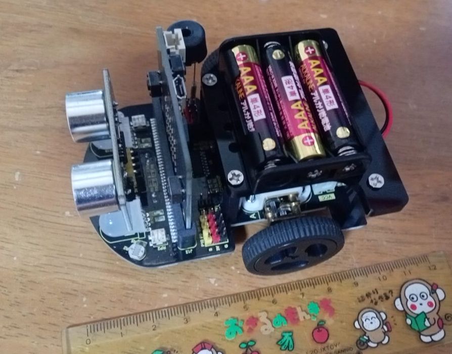
 このロボットカーは電池ボックスを基板に直付けではなく、電池ボックスからの電源ケーブルを基板上のXHコネクタに接続するようになっています。
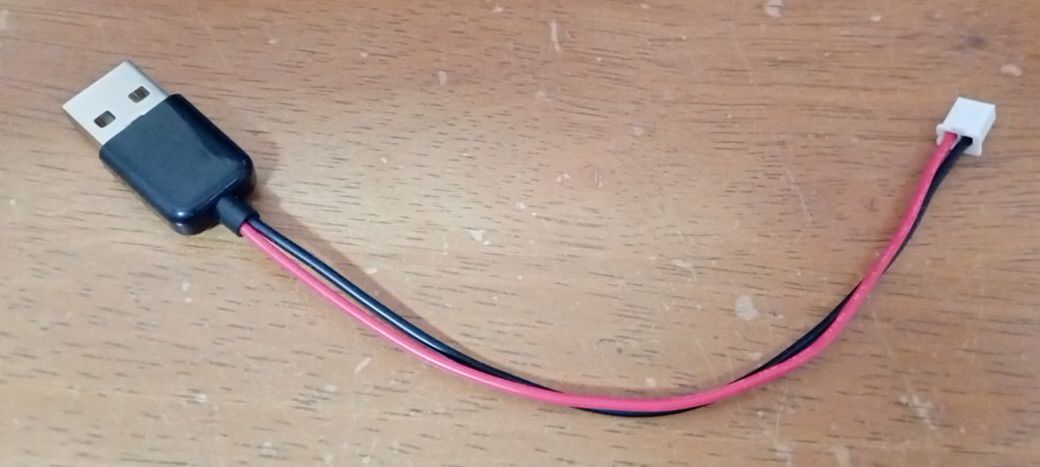
自作のUSB-XHケーブルです。USBケーブルから給電することで基板上のRGB LEDを夜間照明に利用することもできます。
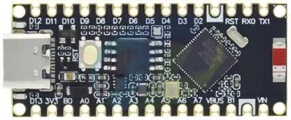
●さらに高機能へ
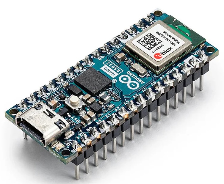
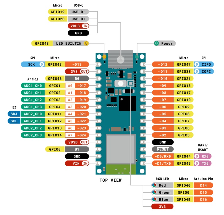
上部ヘッダ   Nano ESP32     エッジコネクタ
3:SCK    ←   1 D13/SCK
5:3V3    ←   2 3V3(OUT)  → 3V3
              3 GPIO46 B0
              4 GPIO1  A0/DAC0
              5 GPIO2  A1        → P0 Photoresistor(right)
              6 GPIO3  A2        → P1 Photoresistor(left)
              7 GPIO4  A3        → P7
              8 GPIO11 A4/SDA    → P20 STC8G1K08
              9 GPIO12 A5/SCL    → P19 STC8G1K08
             10 GPIO13 A6        → P12 TCRT5K(right)
             11 GPIO14 A7        → P13 TCRT5K(left)
             12 VBUS(OUT)
             13 GPIO0  B1
             14 GND       → GND
             15 VIN(IN)   ← 3V3
Qwiic:TX ←  16 GPIO43 D1/TX0
Qwiic:RX ←  17 GPIO44 D0/RX0
4:RST    ←  18 RESET
8:GND    ←  19 GND
             20 GPIO5  D2        → P2
             21 GPIO6  D3        → P3
             22 GPIO7  D4        → P4
             23 GPIO8  D5        → P5
7:DC     ←  24 GPIO9  D6
6:SS     ←  25 GPIO10 D7
             26 GPIO17 D8        → P14 TRIG
             27 GPIO18 D9        → P15 ECHO
             28 GPIO21 D10       → P16 IR Receiver
2:MOSI    ← 29 GPIO38 D11/MOSI
1:MISO    ← 30 GPIO47 D12/MISO
$ pio boards 'NANO ESP32'
========================================================================
ID                  MCU      Frequency  Flash  RAM    Name
------------------  -------  ---------  -----  -----  ------------------
arduino_nano_esp32  ESP32S3  240MHz     16MB   320KB  Arduino Nano ESP32
環境設定ファイルを生成します
$ pio init -b arduino_nano_esp32
arduino_nano_esp32.json で"-DBOARD_HAS_PIN_REMAP" の記述を削除してESP32スタイルのGPIO番号での指定を有効にします。
~/.platformio/platforms/espressif32/boards/arduino_nano_esp32.json
"extra_flags": [
  "-DARDUINO_NANO_ESP32",
  "-DBOARD_HAS_PIN_REMAP", ← 削除
  "-DBOARD_HAS_PSRAM",^
~/.platformio/packages/framework-arduinoespressif32/variants/arduino_nano_nora/pins_arduino.h
#if defined(BOARD_HAS_PIN_REMAP) && !defined(BOARD_USES_HW_GPIO_NUMBERS)
// Arduino style definitions (API uses Dx)
static constexpr uint8_t D0         = 0; // also RX
static constexpr uint8_t D1         = 1; // also TX
......
#else
// ESP32-style definitions (API uses GPIOx)
static constexpr uint8_t D0         = 44; // also RX
static constexpr uint8_t D1         = 43; // also TX
......
$ vi platformio.ini
[env:arduino_nano_esp32]
platform = espressif32
board = arduino_nano_esp32
framework = arduino
board_build.partitions = default_16MB.csv
build_flags =
        -mfix-esp32-psram-cache-issue
        -DCORE_DEBUG_LEVEL=4
board_build.arduino.memory_type = qio_opi
board_build.f_flash = 80000000L
board_build.flash_mode = dio
monitor_speed = 115200
upload_protocol = dfu
upload_port = /dev/ttyACM0
●DFU(Device Firmware Update)モードでアップロードできない場合の対処策
Arduino Nano ESP32互換機は製品によってDFU(Device Firmware Update)モードでアップロードできない場合があります。
$ pio run -e arduino_nano_esp32 -t upload
dfu-util: No DFU capable USB device available
その際には、ESP32 DOWNLOADERを介するとアップロードが可能になります。
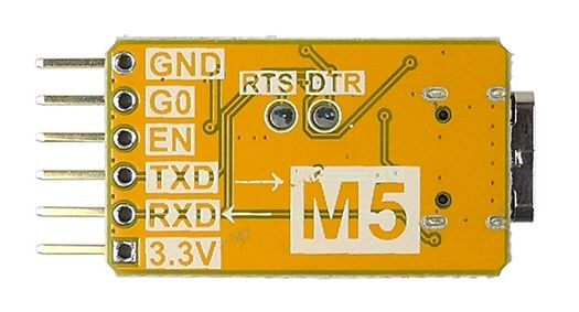
| Downloader | | NANO ESP32 |
| GND | ─ | GND |
| G0 | ─ | GPIO0:B1 |
| EN | ─ | RST |
| TXD | ─ | GPIO44:RX0 |
| RXD | ─ | GPIO43:TX0 |
| 3.3V | ─ | VIN |
$ vi platformio.ini
upload_protocol = dfu
↓
upload_protocol = esptool
;upload_protocol = dfu
........
Checking size .pio/build/arduino_nano_esp32/firmware.elf
Advanced Memory Usage is available via "PlatformIO Home > Project Inspect"
RAM:   [=         ]   9.4% (used 30656 bytes from 327680 bytes)
Flash: [          ]   4.5% (used 292693 bytes from 6553600 bytes)
Building .pio/build/arduino_nano_esp32/firmware.bin
esptool.py v4.9.0
Creating esp32s3 image...
Merged 2 ELF sections
Successfully created esp32s3 image.
Configuring upload protocol...
AVAILABLE: cmsis-dap, dfu, esp-bridge, esp-builtin, esp-prog, espota, esptool, iot-bus-jtag, jlink, minimodule, olimex-arm-usb-ocd, olimex-arm-usb-ocd-h, olimex-arm-usb-tiny-h, olimex-jtag-tiny, tumpa
CURRENT: upload_protocol = esptool
Looking for upload port...
Using manually specified: /dev/ttyACM0
Uploading .pio/build/arduino_nano_esp32/firmware.bin
esptool.py v4.9.0
Serial port /dev/ttyACM0
Connecting....
Chip is ESP32-S3 (QFN56) (revision v0.2)
Features: WiFi, BLE, Embedded PSRAM 8MB (AP_3v3)
Crystal is 40MHz
MAC: xx:xx:xx:xx:xx:xx
Uploading stub...
Running stub...
Stub running...
Changing baud rate to 460800
Changed.
Configuring flash size...
Flash will be erased from 0x00000000 to 0x00003fff...
Flash will be erased from 0x00008000 to 0x00008fff...
Flash will be erased from 0x0000e000 to 0x0000ffff...
Flash will be erased from 0x00010000 to 0x00057fff...
SHA digest in image updated
Compressed 14032 bytes to 9808...
Writing at 0x00000000... (100 %)
Wrote 14032 bytes (9808 compressed) at 0x00000000 in 0.3 seconds (effective 373.8 kbit/s)...
Hash of data verified.
Compressed 3072 bytes to 146...
Writing at 0x00008000... (100 %)
Wrote 3072 bytes (146 compressed) at 0x00008000 in 0.0 seconds (effective 1563.9 kbit/s)...
Hash of data verified.
Compressed 8192 bytes to 47...
Writing at 0x0000e000... (100 %)
Wrote 8192 bytes (47 compressed) at 0x0000e000 in 0.0 seconds (effective 2494.9 kbit/s)...
Hash of data verified.
Compressed 293056 bytes to 167702...
Writing at 0x00010000... (9 %)
Writing at 0x0001b94e... (18 %)
Writing at 0x00024795... (27 %)
Writing at 0x00029e7f... (36 %)
Writing at 0x0002f315... (45 %)
Writing at 0x0003469d... (54 %)
Writing at 0x00039d90... (63 %)
Writing at 0x0004269c... (72 %)
Writing at 0x0004ae71... (81 %)
Writing at 0x0005048b... (90 %)
Writing at 0x0005601c... (100 %)
Wrote 293056 bytes (167702 compressed) at 0x00010000 in 3.9 seconds (effective 596.7 kbit/s)...
Hash of data verified.

Leaving...
Hard resetting via RTS pin...
●単なる電力供給車として使う
単4電池3本搭載のロボットカーは降圧回路を経由して、micro:bitエッジコネクタに 3.3V を供給しています。
そこで、3.3V駆動のESP32マイコンへの電力供給車として使ってしまいます。
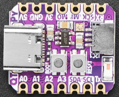 Adafruit QT Py ESP32-S2の5V端子は外部電源からの電圧入力として使用することもできますが、電源への逆流防止にショットキーダイオードを経由する必要があります。
また5V端子からUSBポートに電源を供給することはできません。保護ダイオードが内蔵されており、5VがUSBコネクタに供給されるのを防いでいます。
Adafruit QT Py ESP32-S2の5V端子は外部電源からの電圧入力として使用することもできますが、電源への逆流防止にショットキーダイオードを経由する必要があります。
また5V端子からUSBポートに電源を供給することはできません。保護ダイオードが内蔵されており、5VがUSBコネクタに供給されるのを防いでいます。
micro:bitユニバーサル基板の前面にはQT-Py ESP32-S2とAdafruit 320x240 IPS TFT(ST7789)を取り付けています
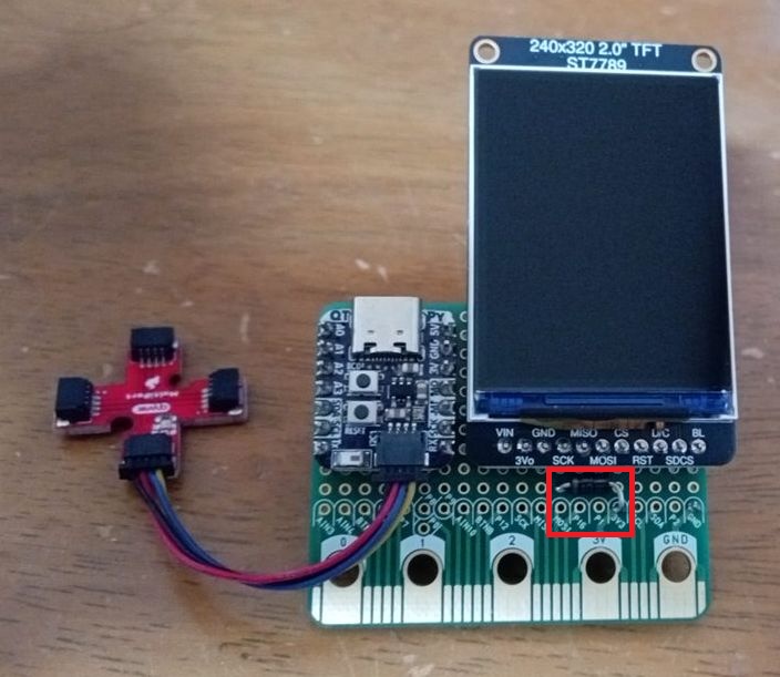
QT Py ESP32-S2のGNDと3.3V端子のみをエッジコネクタに接続しています。
当初、エッジコネクタの3.3Vとの間に1N5817ショットキーバリアダイオードを取り付けていましたが、これにより、0.4V程度の電圧降下が発生します。
QT Py 3.3V端子入力電圧が3Vを多少下回っても動作しますが、周辺機器を接続すると不安定になります。
そこで、ジャンパーピンをショートさせる方式に変更しました。
QT Py のUSB端子から給電する場合は忘れずにピンを外します。
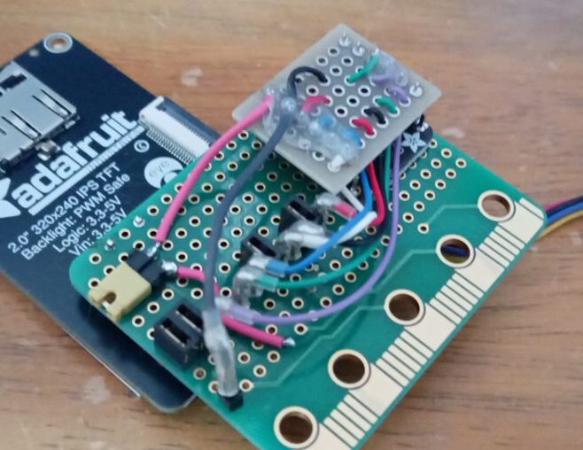
裏側はこんな感じです
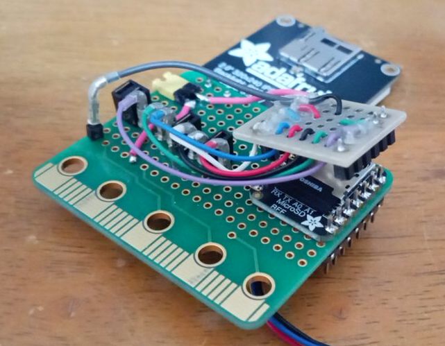
Adafruit IPS TFT に実装されているmicrSDカードスロットは読み取り用なので、別途、
Adafruit microSD Card BFF を取り付けています
|
 Raspberry Pi(ラズベリー パイ)は、ARMプロセッサを搭載したシングルボードコンピュータ。イギリスのラズベリーパイ財団によって開発されている。
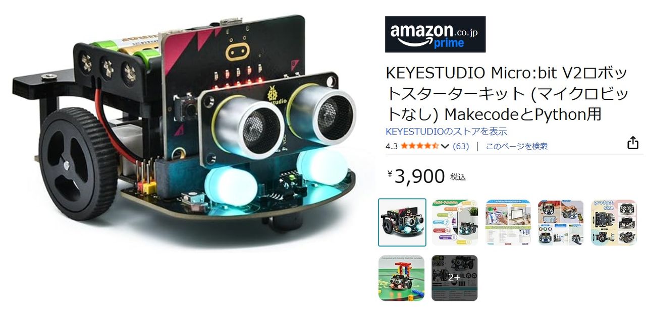
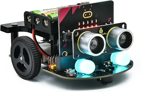 KEYESTUDIO Micro:bit V2ロボットスターターキット (マイクロビットなし) MakecodeとPython用
動き、光と音の使い方、障害物の検知と回避方法、線をたどり、IRリモコンとアプリでコントロールする方法を学びます。
 Maqueen Lite V5 micro:bit ロボットキット STEM用(ライントレース&障害物回避)
Maqueen Lite V5 STEMロボットは、事前調整済みのライントレースアルゴリズム、耐衝撃モーター、開封即使用可能な設計で、ストレスを解消します。
 たいていのことは100日あれば、うまくいく。長田英知著
「時間がなくて、なかなか自分のやりたいことができない」
「一念発起して何かを始めても、いつも三日坊主で終わってしまう」
「色んなことを先延ばしにしたまま、時間だけが過ぎていく」
そこで本書では、そんな著者が独自に開発した、
まったく新しい目標達成メソッド「100日デザイン」について、
その知識と技術を、余すところなくご紹介します。
 まんがで納得ナポレオン・ヒル 思考は現実化する
OLとして雑務をこなす日々に飽き足らず、科学者だった父が残した薬品を商品化すべく、起業を決意した内山麻由(27)。彼女はセミナーで知り合った謎の女性からサポートを得ながら、彼女と二人三脚でナポレオン・ヒルの成功哲学を実践し、さまざまな問題を乗り越えていく。
ヒル博士の<ゴールデンルール>に従い、仕事に、恋に全力疾走する彼女の、成功への物語。
 今日は人生最悪で最高の日 1秒で世界を変えるたったひとつの方法 ひすいこたろう著
偉人の伝記を読むと、最悪な日は、不幸な日ではなく、新しい自分が始まる日であることがわかります。最悪な出来事は、自分の人生が、想像を超えて面白くなる兆しなのです。偉人伝を読むことで、このときの不幸があったおかげで、未来にこういう幸せがくるのかと、人生を俯瞰する視線が立ち上がるのです。
 ご飯は私を裏切らない heisoku著
辛い現実から目を背けて食べるご飯は、いつも美味しく幸せを届けてくれる。
29歳、中卒、恋人いない歴イコール年齢。バイト以外の職歴もなく、短期バイトを転々とする日々。ぐるぐると思索に耽るけど、ご飯を食べると幸せになれる。奇才の新鋭・heisokuが贈るリアル労働グルメ物語!
 【最新版Gemini 3に対応!】できるGemini (できるシリーズ)
Geminiを「最強の知的生産パートナー」として使いこなすための、実践的なノウハウを凝縮した一冊です。
基本的な操作方法から、具体的なビジネスシーンでの活用、日々の業務を自動化するGoogle Workspaceとの連携、さらには自分だけのオリジナルAIを作成する方法まで余すところなく解説します。
 Rustプログラミング完全ガイド 他言語との比較で違いが分かる!
Rustの各手法や考え方を幅広く解説!
500以上のサンプルを掲載。実行結果も確認。
全24章の包括的なチュートリアル。
 ポチらせる文章術
販売サイト・ネット広告・メルマガ・ブログ・ホームページ・SNS…
全WEB媒体で効果バツグン!
カリスマコピーライターが教える「見てもらう」「買ってもらう」「共感してもらう」すべてに効くネット文章術
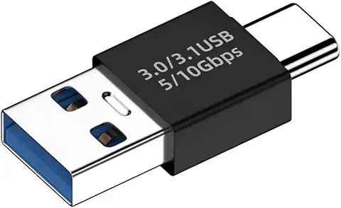 小型で便利な Type-C アダプター USB C オス - USB3.1 オスアダプター
Type-C端子のマイコンボードをこのアダプタを介して直接Raspberry Piに挿すことができます。ケーブルなしで便利なツールです。
 Divoom Ditoo Pro ワイヤレススピーカー
15W高音質重低音/青軸キーボード/Bluetooth5.3/ピクセルアート 専用アプリ/USB接続/microSDカード
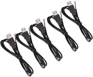 電源供給USBケーブル スリム 【5本セット】
USB電源ケーブル 5V DC電源供給ケーブル スリム 【5本セット】 電源供給 バッテリー 修理 自作 DIY 電子工作 (100cm)
|